|
Author
|
Message
|
|
capelo
|
|
|
Group: Forum Members
Last Active: 6 Years Ago
Posts: 279,
Visits: 4.5K
|
While I have the engine material in the machine shop, I wanted to advance some work, I would like to balance everything possible and I want to start with the pistons, I have thought them and they are between 757 and 759gr, the scale only needs one gram, tomorrow they bring me one of 0.01gr, the case is that I do not know if it is a great imbalance and if it is where I have to act to match weights 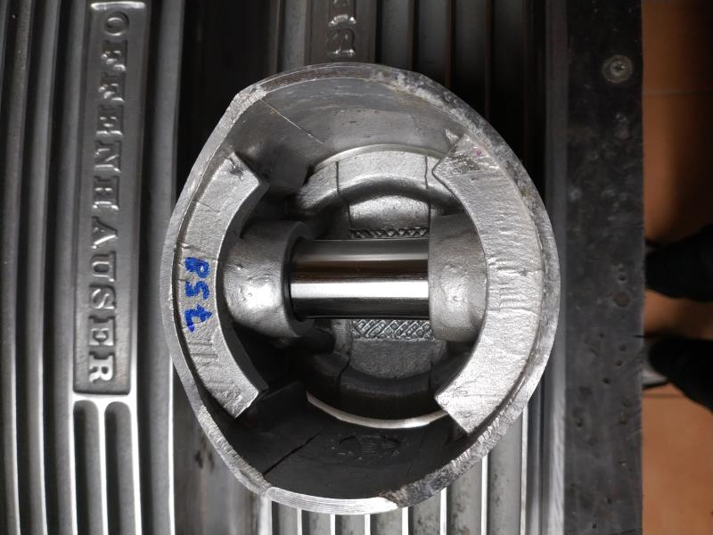 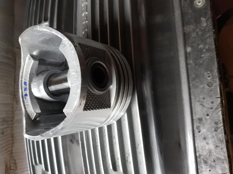
|
|
|
|
|
Ted
|
|
|
Group: Administrators
Last Active: 6 hours ago
Posts: 7.6K,
Visits: 206.0K
|
If you get all the various parts within ½ gram or less, you’ll be good to go. Getting it as close to zero that you can is always the target though. Be sure to include the wrist pin with the piston to help minimize weight stack ups on the various parts. That will require keeping the wrist pins with their respective pistons which is recommended anyhow depending upon how they were pin fitted at the manufacturer.
  Lorena, Texas (South of Waco) Lorena, Texas (South of Waco)
|
|
|
|
|
capelo
|
|
|
Group: Forum Members
Last Active: 6 Years Ago
Posts: 279,
Visits: 4.5K
|
Ted (2/11/2020)
If you get all the various parts within ½ gram or less, you’ll be good to go. Getting it as close to zero that you can is always the target though. Be sure to include the wrist pin with the piston to help minimize weight stack ups on the various parts. That will require keeping the wrist pins with their respective pistons which is recommended anyhow depending upon how they were pin fitted at the manufacturer. thanks Ted, seeing the images where I can act to match the weights? Can I polish the part of the skirt where the number?
|
|
|
|
|
Ted
|
|
|
Group: Administrators
Last Active: 6 hours ago
Posts: 7.6K,
Visits: 206.0K
|
The design and construction of the piston will determine where the best areas of the piston are for any weight reductions that must be performed. With that said, then the type of tools or machinery that’s available will dictate how the weight is removed. In your case, a lathe or milling machine can be used to machine the cast lips below the wrist pin on the inner edge of the skirt. A milling machine equipped with a long end mill or cutter can be used to catch the thick portion behind the ring lands but care must be taken to not make anything so thin as to weaken or damage the piston. While I’m not a big advocate of using a drill for weight reduction in the pistons, it can be used if used prudently. Although not recommended as a normal weight reduction operation for pistons, drill bits are often used by the uninformed to remove weight in the deck portion of the piston and that can create stress risers there. Nothing says you can’t use a drill on that lip on the bottom and inner portion of the piston. You have to be careful in not going too deep with the drill. Doing a multitude of shallow indentations with the drill bit will be much better strength wise than doing a fewer number of deeper holes. Because you are only working with removing only two grams on some of the pistons, overall weight reduction is not going to be a major deal.
Lorena, Texas (South of Waco)
|
|
|
|
|
capelo
|
|
|
Group: Forum Members
Last Active: 6 Years Ago
Posts: 279,
Visits: 4.5K
|
Ted (2/13/2020)
The design and construction of the piston will determine where the best areas of the piston are for any weight reductions that must be performed. With that said, then the type of tools or machinery that’s available will dictate how the weight is removed. In your case, a lathe or milling machine can be used to machine the cast lips below the wrist pin on the inner edge of the skirt. A milling machine equipped with a long end mill or cutter can be used to catch the thick portion behind the ring lands but care must be taken to not make anything so thin as to weaken or damage the piston. While I’m not a big advocate of using a drill for weight reduction in the pistons, it can be used if used prudently. Although not recommended as a normal weight reduction operation for pistons, drill bits are often used by the uninformed to remove weight in the deck portion of the piston and that can create stress risers there. Nothing says you can’t use a drill on that lip on the bottom and inner portion of the piston. You have to be careful in not going too deep with the drill. Doing a multitude of shallow indentations with the drill bit will be much better strength wise than doing a fewer number of deeper holes. Because you are only working with removing only two grams on some of the pistons, overall weight reduction is not going to be a major deal. thanks Ted for the explanation, apart from the areas you have indicated, can I work on the surfaces that I indicate with the arrows? 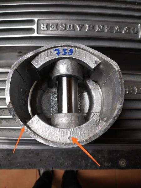
|
|
|
|
|
capelo
|
|
|
Group: Forum Members
Last Active: 6 Years Ago
Posts: 279,
Visits: 4.5K
|
I have already brought the heads of the machine, I have to give it a good wash and start assembling, any advice? 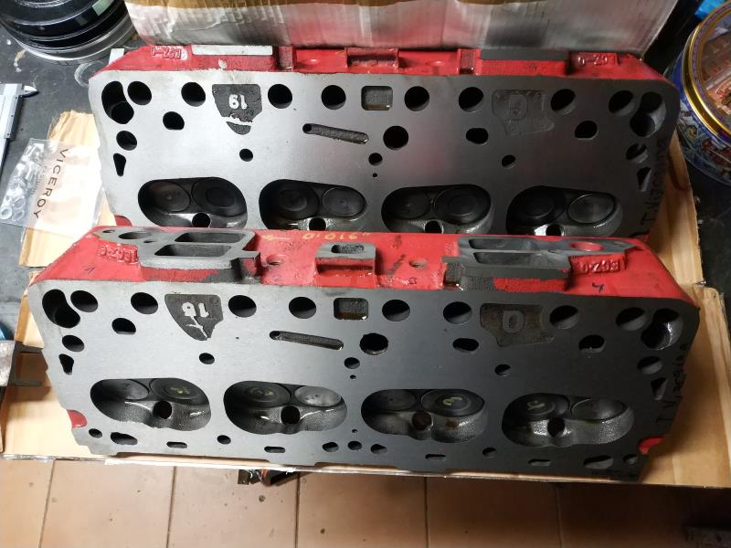 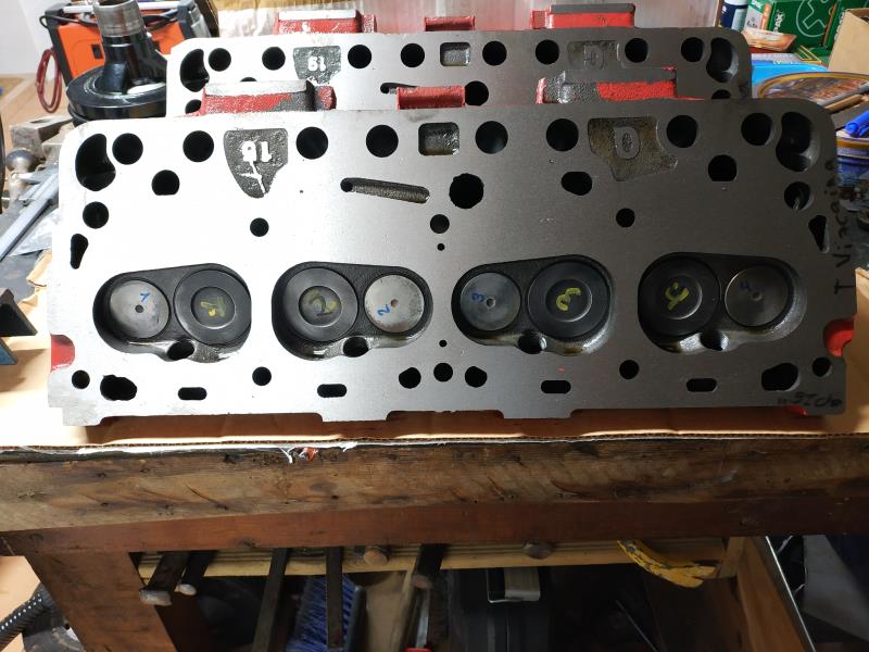
|
|
|
|
|
capelo
|
|
|
Group: Forum Members
Last Active: 6 Years Ago
Posts: 279,
Visits: 4.5K
|
|
|
|
|
|
capelo
|
|
|
Group: Forum Members
Last Active: 6 Years Ago
Posts: 279,
Visits: 4.5K
|
I have seen this to relieve space, what do you think? 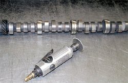
|
|
|
|
|
Ted
|
|
|
Group: Administrators
Last Active: 6 hours ago
Posts: 7.6K,
Visits: 206.0K
|
In regards to the picture asking where to take the material off of the piston for weight matching purposes, concentrate only on the inner lip. Keep away from the skirt or outer portion of the piston. On that rear cam bearing where both holes do not align with the holes in the block, you will need to modify the bearing so that the hole for the distributor shaft is open to the bearing. On your ‘old’ camshaft with the added grooves, you only need one or two of the journals with a ‘cutting’ groove. My preference is to only groove the second from last journal when making a cutting tool for the bearings. If it’s a front or rear cam bearing that needs some material removed, then I’ll cut a groove in the end cam journal of the ‘tool’ I’m using or just use a bearing knife to cut the bearing manually. Having the cut itself diagonal as you show in your picture is good as it increases the cutting area as well as allowing the bearing material to clean itself from the groove in the ‘tool’ much easier. Also when adding the groove to the old camshaft, cut it at an angle or not perpendicular to the journal surface so you have a sharp cutting edge when turning only in one direction. This allows the ‘tool’ to be installed turning it opposite of the cutting direction so it can be placed at the appropriate bearing without necessarily cutting on bearings that may not need any material removed from them. Before doing any cutting on the cam bearings, put the new camshaft in the block from the front and rear using the respective journals on the camshaft. Assuming those fit and turn fine, this points to the tightness of your camshaft then being on one of the center three cam bearings. Then take the camshaft and work it in the two journals from both the front and rear. If the camshaft still turns freely doing this, then the center cam bearing is suspect but this does not rule out a crooked cam tunnel. I typically don’t see crooked cam tunnels on the 272/292 engines but there’s a first time for everything. I would come closer to seeing a cam bearing that’s installed slightly crooked or ‘cocked’ but an undersize hole in the block can also make fitment tighter than normal.
Lorena, Texas (South of Waco)
|
|
|
|
|
capelo
|
|
|
Group: Forum Members
Last Active: 6 Years Ago
Posts: 279,
Visits: 4.5K
|
Ted (2/15/2020)
In regards to the picture asking where to take the material off of the piston for weight matching purposes, concentrate only on the inner lip. Keep away from the skirt or outer portion of the piston. On that rear cam bearing where both holes do not align with the holes in the block, you will need to modify the bearing so that the hole for the distributor shaft is open to the bearing. On your ‘old’ camshaft with the added grooves, you only need one or two of the journals with a ‘cutting’ groove. My preference is to only groove the second from last journal when making a cutting tool for the bearings. If it’s a front or rear cam bearing that needs some material removed, then I’ll cut a groove in the end cam journal of the ‘tool’ I’m using or just use a bearing knife to cut the bearing manually. Having the cut itself diagonal as you show in your picture is good as it increases the cutting area as well as allowing the bearing material to clean itself from the groove in the ‘tool’ much easier. Also when adding the groove to the old camshaft, cut it at an angle or not perpendicular to the journal surface so you have a sharp cutting edge when turning only in one direction. This allows the ‘tool’ to be installed turning it opposite of the cutting direction so it can be placed at the appropriate bearing without necessarily cutting on bearings that may not need any material removed from them. Before doing any cutting on the cam bearings, put the new camshaft in the block from the front and rear using the respective journals on the camshaft. Assuming those fit and turn fine, this points to the tightness of your camshaft then being on one of the center three cam bearings. Then take the camshaft and work it in the two journals from both the front and rear. If the camshaft still turns freely doing this, then the center cam bearing is suspect but this does not rule out a crooked cam tunnel. I typically don’t see crooked cam tunnels on the 272/292 engines but there’s a first time for everything. I would come closer to seeing a cam bearing that’s installed slightly crooked or ‘cocked’ but an undersize hole in the block can also make fitment tighter than normal. Ok, I'll make those checks before making the cuts. On the rear bearing I am in fact able to take it out, make a new hole and reinsert. On the pistons I will focus on the Waves indicated by you. Thank you
|
|
|
|