|
By capelo - 7 Years Ago
|
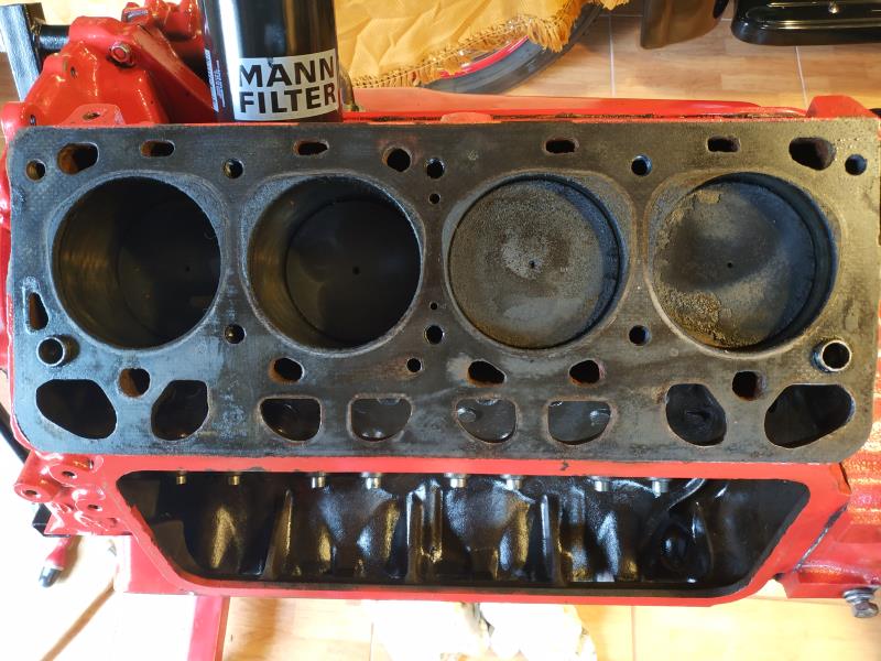
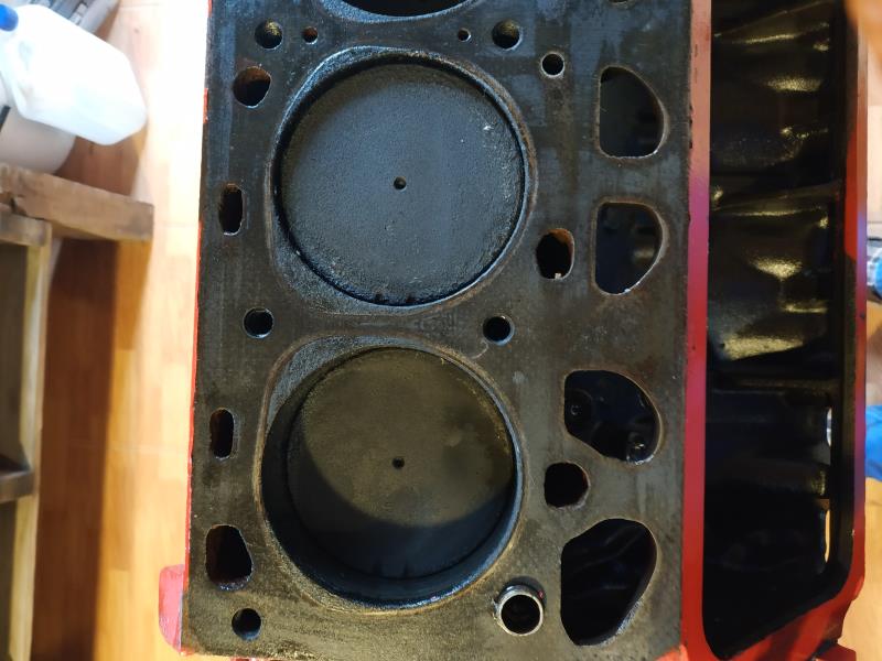
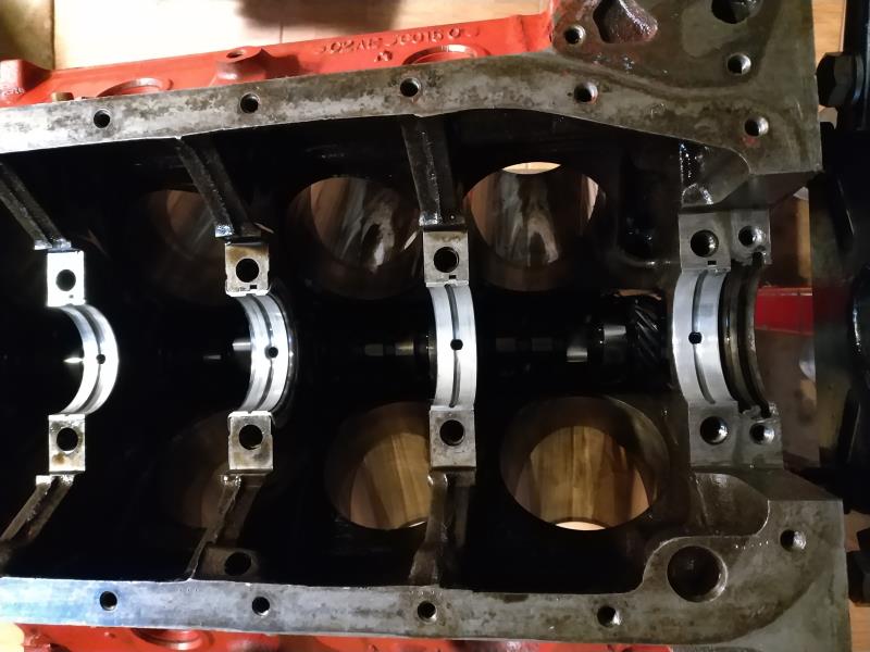
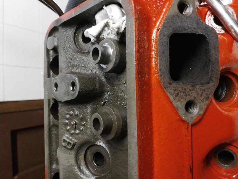
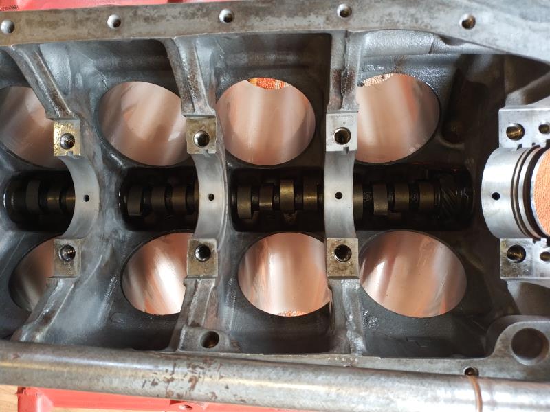
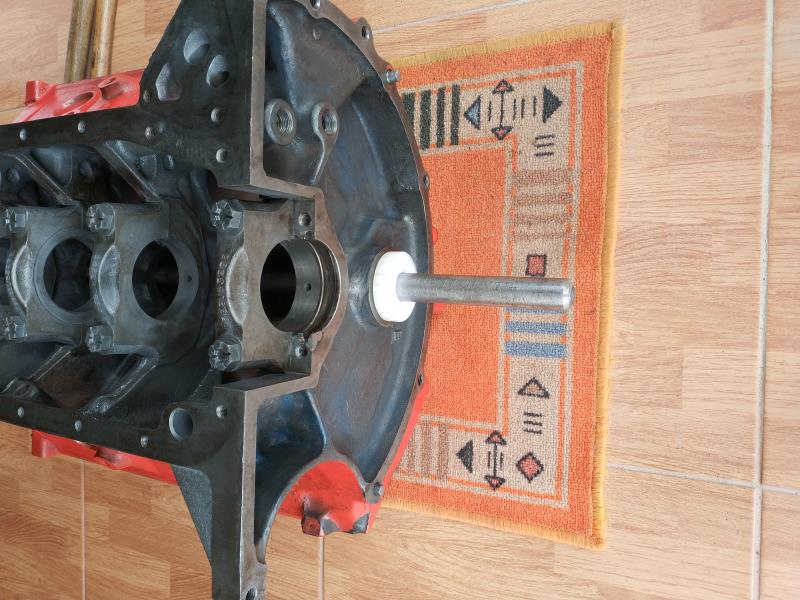
Hola, estoy iniciando mi restauración y me gustaría una opinión sobre lo que estoy encontrando en el desmontaje, pongo fotos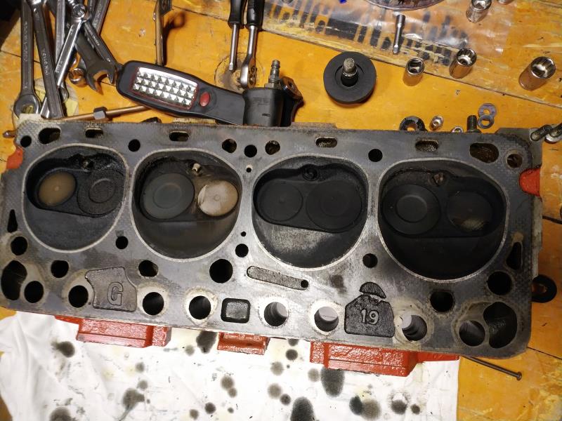
|
|
By Cliff - 7 Years Ago
|
|
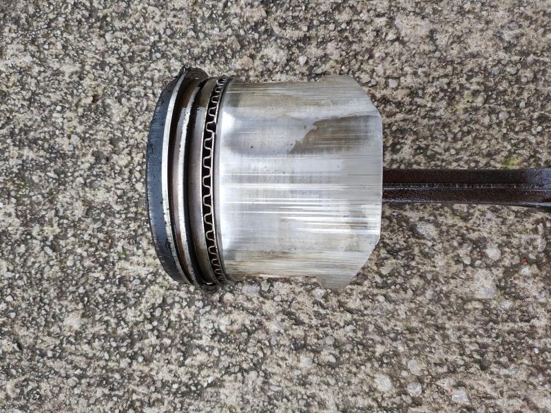
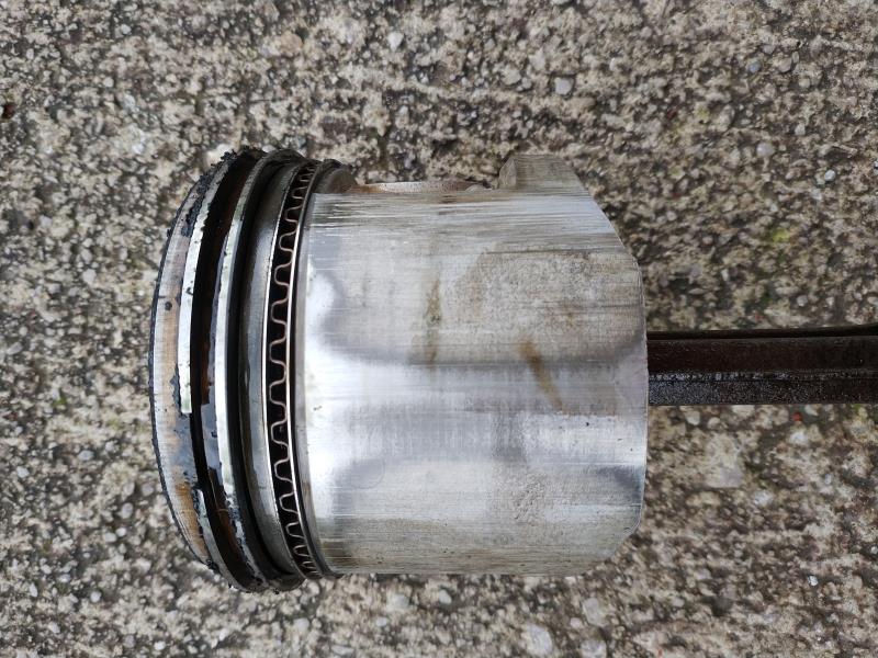
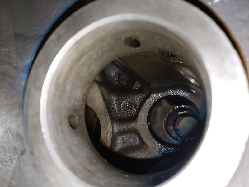
Looks like an oil burner
|
|
By capelo - 7 Years Ago
|
|
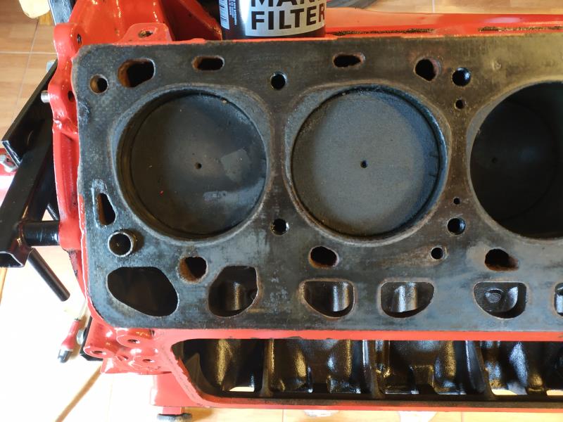
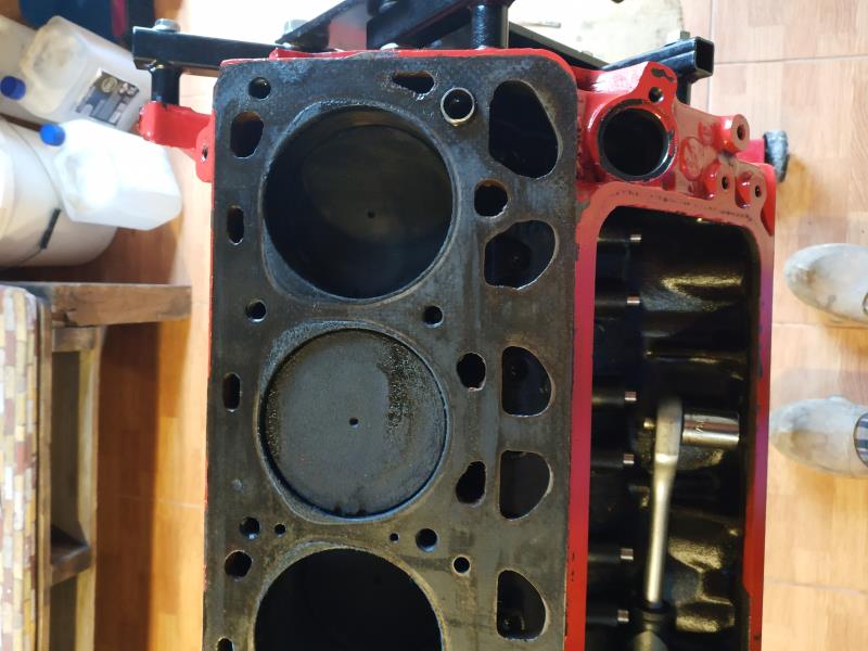
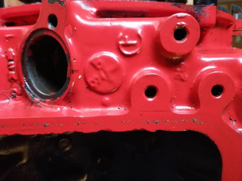
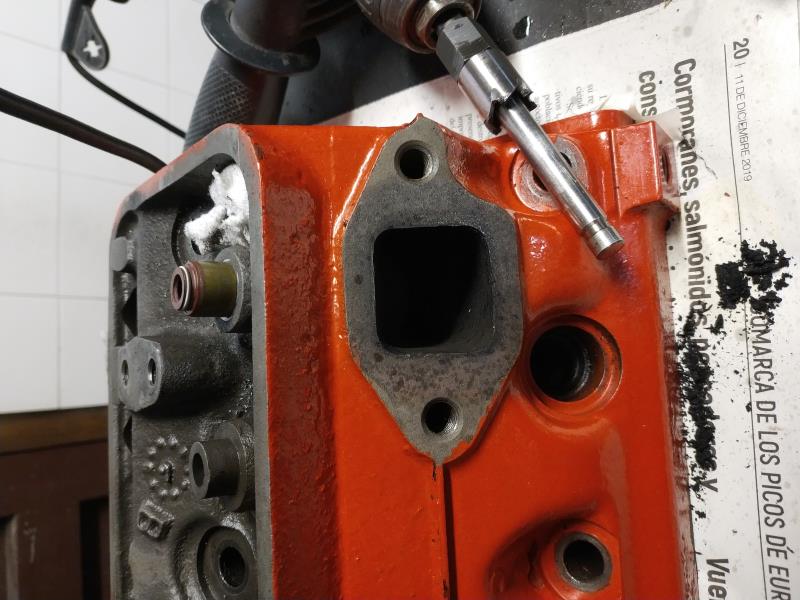
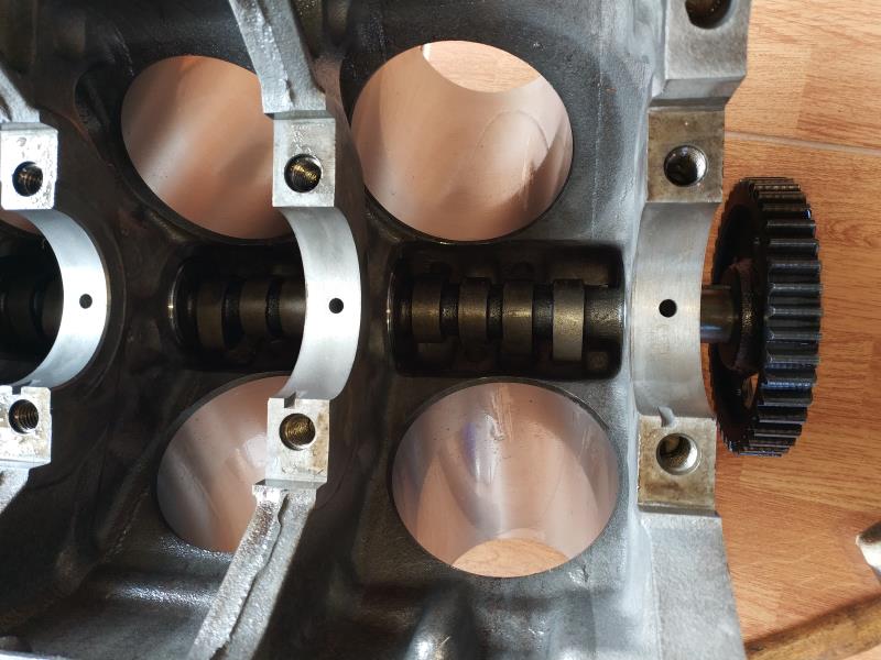
That seemed to me, what are those two small holes in the center?
|
|
By Ted - 7 Years Ago
|
capelo (12/7/2019)
..... What are those two small holes in the center?
Those are ‘steam holes’. They were put in the deck surface and the heads starting in 1960 to get rid of an air pocket that could potentially form between those two cylinders in the block. While they are sometimes referred to as cooling holes, they are not large enough to aid in any additional cooling at that particular area. I have found the cylinder heads cracked at those steam holes so it’s questionable if that was a good idea or not.
Those added holes were installed at the same time that the low profile radiators started being used on the cars. My experience has been that the ‘steam holes’ holes are not needed on trucks and vehicles that have the taller profile radiators. The earlier vehicles and pickups with the tall radiators were not as prone to those air locks in the block as those vehicles that were supplied with low profile radiators (1960-1962 Ford cars with the 292 engines). While the Fel-Pro gasket sets are supplied with instructions to drill the blocks and the heads with the added holes if they do not have them, I recommend against doing that. I go out of my way to plug those 'steam holes' holes in those blocks that do have them when using heads that are not drilled for those holes.
If you already have the holes in both the heads and the block, then just make sure they are clean when reassembling the engine and use them.
|
|
By Ted - 7 Years Ago
|
|
capelo (12/7/2019)
...... what are those two small holes in the center?
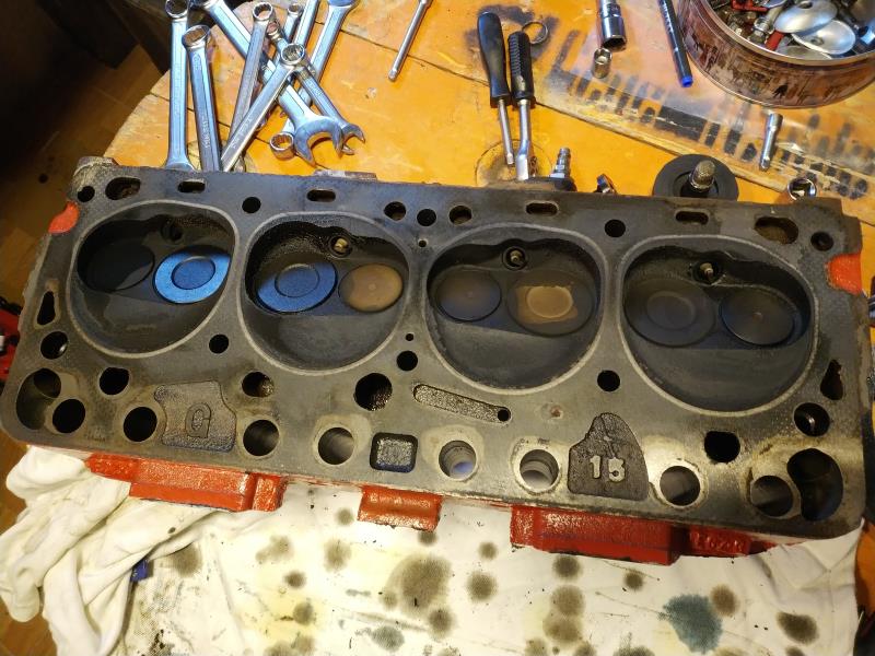
In looking at the picture of your cylinder head, it would appear that the two small center holes (‘steam holes’) have been added. If that’s a ‘G’ head, then it came from the factory without the additional ‘steam holes’.
|
|
By KULTULZ - 7 Years Ago
|
|
In looking at the picture of your cylinder head, it would appear that the two small center holes (‘steam holes’) have been added. If that’s a ‘G’ head, then it came from the factory without the additional ‘steam holes’.
... hmmpf ...
So that explains 1960-62 PASS CAR heads with C0AE and C1AE prefixes? The steam holes on the head shown, is this the FEL-PRO modification do you think? Have never been able to find FEL-PRO instruction sheet.
THANX! Learn something new here about everyday.
|
|
By capelo - 7 Years Ago
|
Ted (12/7/2019)
capelo (12/7/2019)
..... What are those two small holes in the center? Those are ‘steam holes’. They were put in the deck surface and the heads starting in 1960 to get rid of an air pocket that could potentially form between those two cylinders in the block. While they are sometimes referred to as cooling holes, they are not large enough to aid in any additional cooling at that particular area. I have found the cylinder heads cracked at those steam holes so it’s questionable if that was a good idea or not. Those added holes were installed at the same time that the low profile radiators started being used on the cars. My experience has been that the ‘steam holes’ holes are not needed on trucks and vehicles that have the taller profile radiators. The earlier vehicles and pickups with the tall radiators were not as prone to those air locks in the block as those vehicles that were supplied with low profile radiators (1960-1962 Ford cars with the 292 engines). While the Fel-Pro gasket sets are supplied with instructions to drill the blocks and the heads with the added holes if they do not have them, I recommend against doing that. I go out of my way to plug those 'steam holes' holes in those blocks that do have them when using heads that are not drilled for those holes.
If you already have the holes in both the heads and the block, then just make sure they are clean when reassembling the engine and use them.
good morning Ted and thanks for the explanations, I have holes in heads and block, I have to pass everything through the machine so if it is better to remove them I can do it I have seen how it is done in the blocks but I do not know if it can be done from it Heads form. In another order of things I would like to post the entire modification process in the forum but I don't know if this is the site. thanks
|
|
By capelo - 7 Years Ago
|
|
|
By capelo - 7 Years Ago
|
|
|
By capelo - 7 Years Ago
|
|
|
By capelo - 7 Years Ago
|
|
|
By capelo - 7 Years Ago
|
|
|
By capelo - 7 Years Ago
|
only two head bolt sizes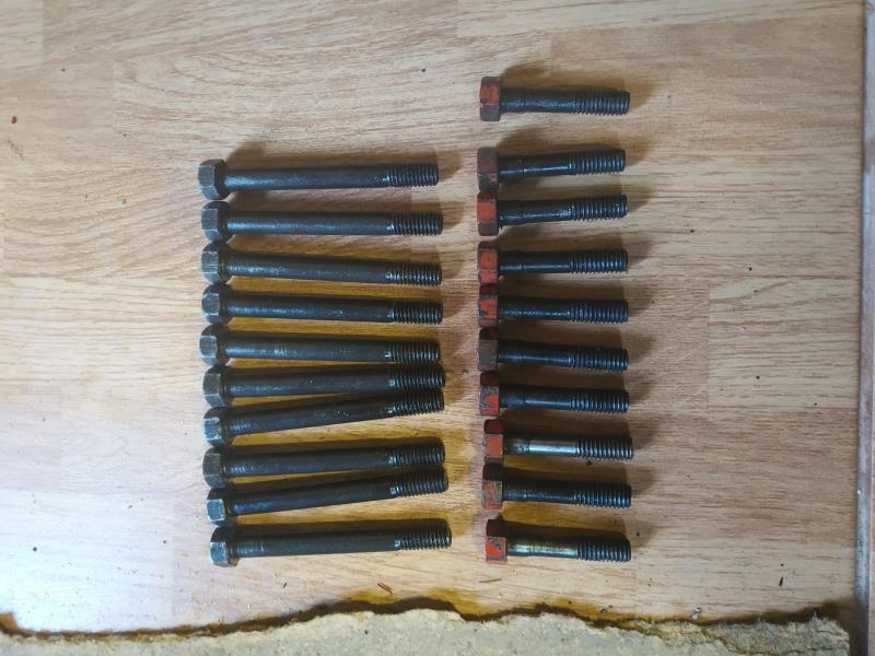
|
|
By capelo - 7 Years Ago
|
|
|
By darrell - 7 Years Ago
|
|
the block would have came with the holes.i had the same setup years ago and drilled the holes in a set of g heads.i never bothered after that.ive noticed over the years that a lot of new ideas for y blocks were dropped later.
|
|
By capelo - 7 Years Ago
|
|
|
By capelo - 7 Years Ago
|
|
|
By charliemccraney - 7 Years Ago
|
|
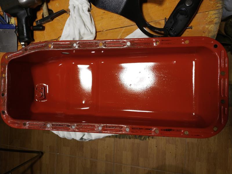
If the paint is not designed for continuous contact / submersion in oil, then every bit of it needs to be stripped from the inside of the oil pan.
|
|
By capelo - 7 Years Ago
|
[cita] [b] charliemccraney (12/08/2019) [/ b]
Si la pintura no está diseñada para un contacto continuo / inmersión en aceite, entonces cada parte debe ser eliminada del interior del cárter de aceite. [/ citar]
la bandeja de aceite parece estar recubierta de polvo
|
|
By charliemccraney - 7 Years Ago
|
|
Just the same. You do not want it to deteriorate and flake of and clog the oil pickup or get into the oiling system.
|
|
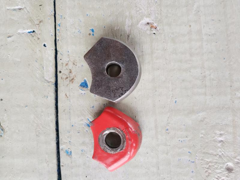
By capelo - 7 Years Ago
|
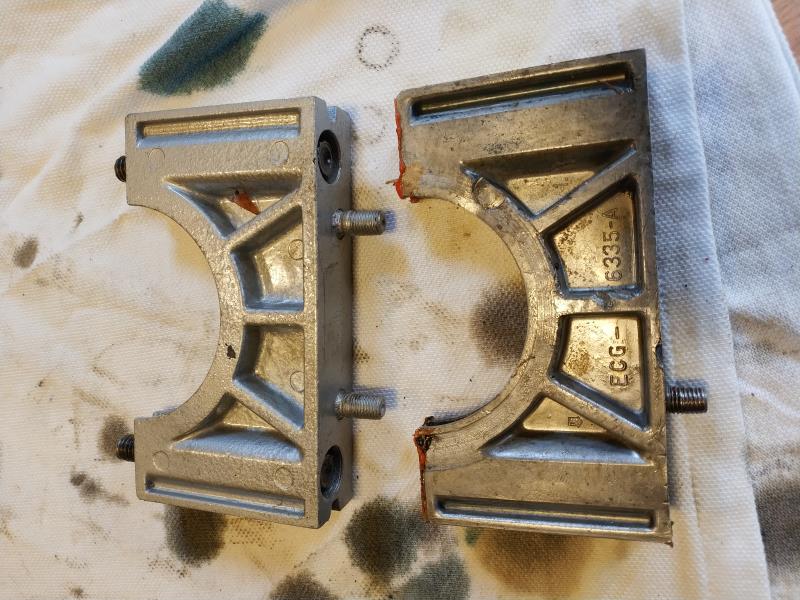
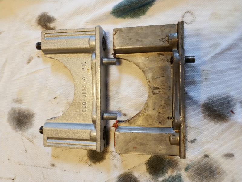
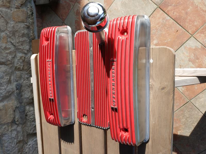
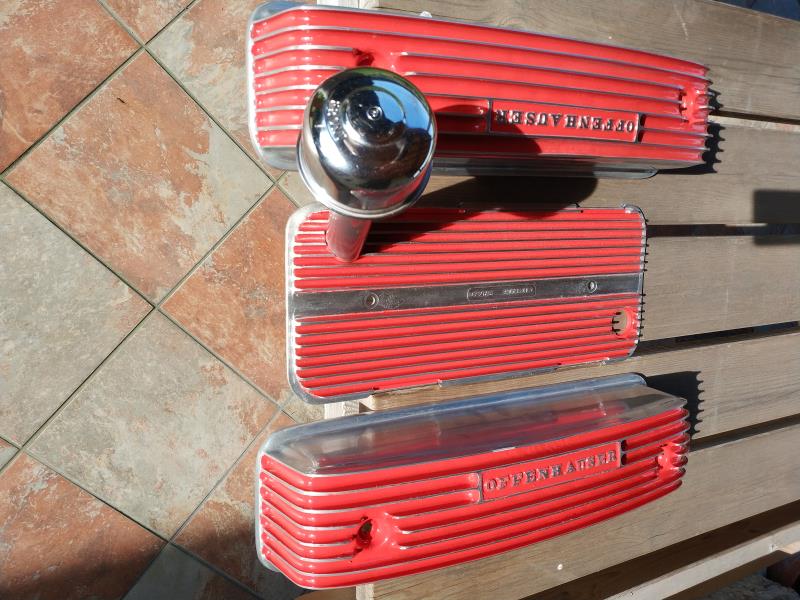
the old one seems somewhat deformed, the one at the top can be the spare part ..
|
|
By capelo - 7 Years Ago
|
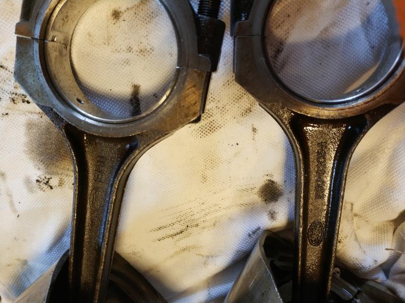 different but the same? different but the same?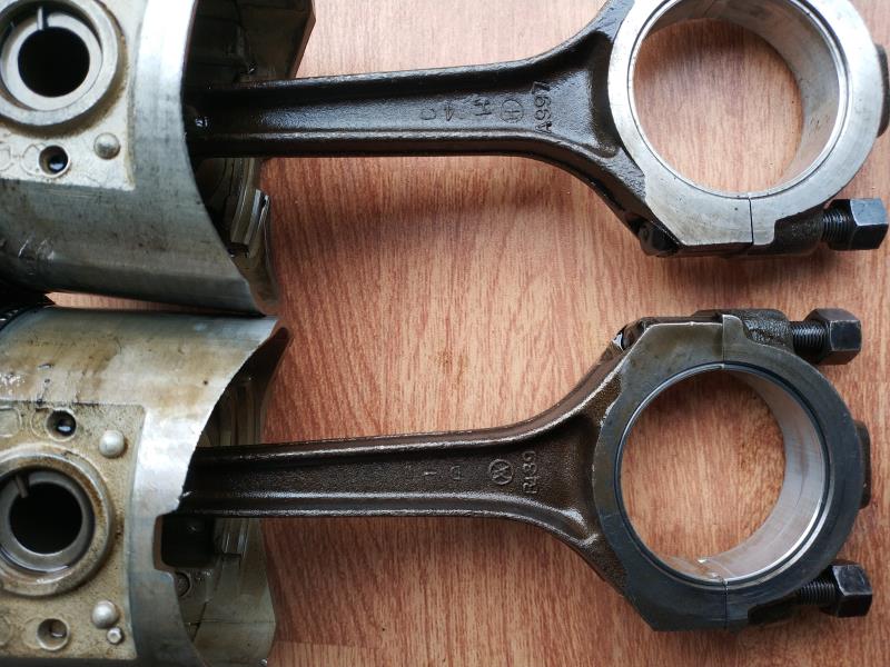
|
|
By capelo - 7 Years Ago
|
|
|
By Ted - 7 Years Ago
|
capelo (12/9/2019)
The old one seems somewhat deformed, The one at the top can be the spare part . 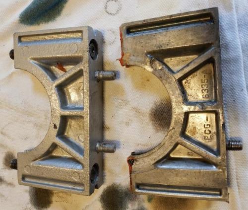
There’s no 'top' rear seal retainer on my screen but the one on the right (has only one oil pan stud) would appear to have been damaged by a flywheel bolt that was too long. Be sure the flywheel bolts do not protrude beyond the thickness of the crankshaft flywheel flange when bolting up the flywheel.
|
|
By Ted - 7 Years Ago
|
capelo (12/9/2019)
Different but the same? 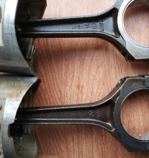
Look for ‘EBU’ on the opposite sides of the rods. If ‘EBU’ is present, they are the same. Beyond that, as long as the rods are the same length and the small/big end weights are reasonably close as a set, they can be used as a set after rebuilding and balancing.
|
|
By capelo - 7 Years Ago
|
|
|
By capelo - 7 Years Ago
|
Can this be a problem?

|
|
By capelo - 7 Years Ago
|
there is a small difference ...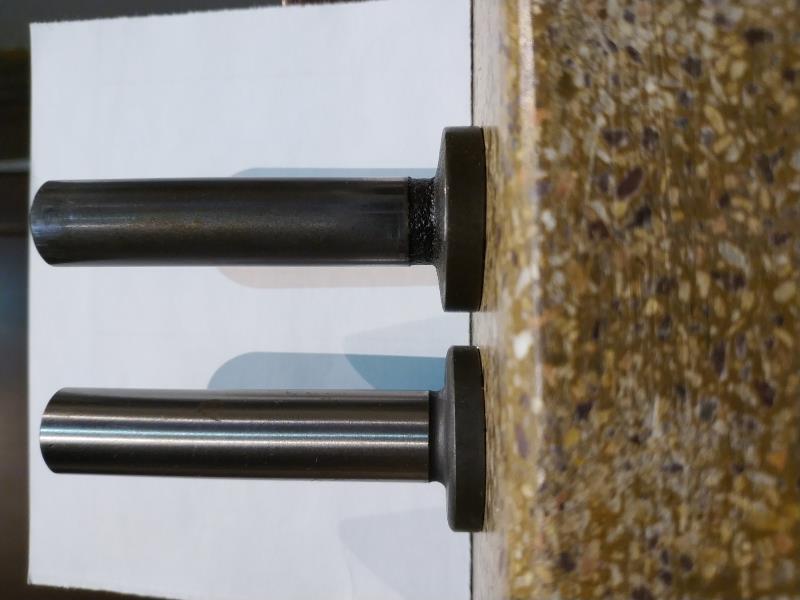
|
|
By capelo - 7 Years Ago
|
|
there is a small difference ...
|
|
By capelo - 7 Years Ago
|
how do they look?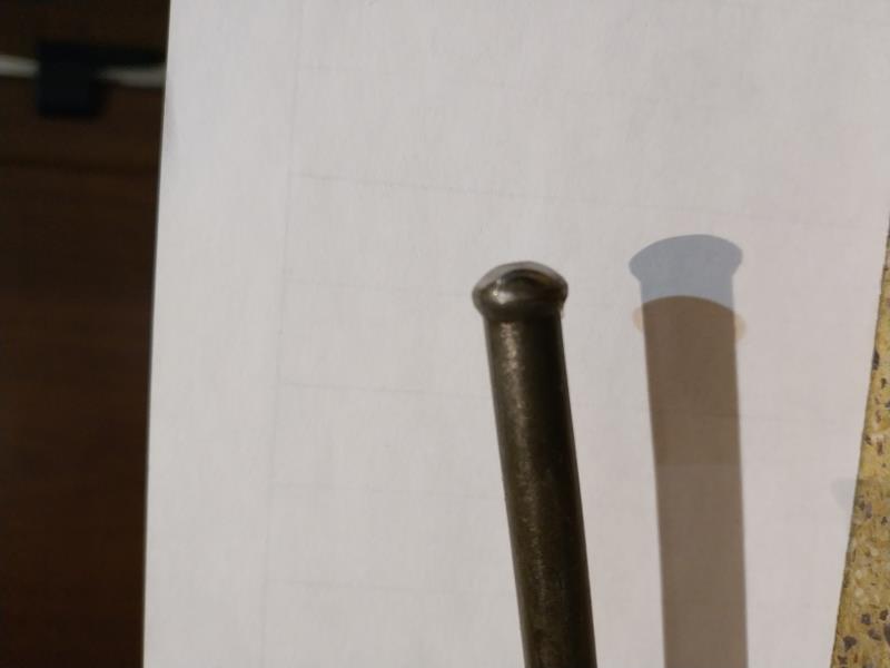 
|
|
By capelo - 7 Years Ago
|
Ted (12/9/2019)
capelo (12/9/2019)
The old one seems somewhat deformed, The one at the top can be the spare part . There’s no 'top' rear seal retainer on my screen but the one on the right (has only one oil pan stud) would appear to have been damaged by a flywheel bolt that was too long. Be sure the flywheel bolts do not protrude beyond the thickness of the crankshaft flywheel flange when bolting up the flywheel.
I thought that the photo was rotated by the above, the old one is the one on the right and the replacement on the left, now the bolts are the same and do not interfere I do not know if in the past, but it is deformed in the center and in side slots
|
|
By capelo - 7 Years Ago
|
Ted (12/9/2019)
capelo (12/9/2019)
Different but the same? Look for ‘EBU’ on the opposite sides of the rods. If ‘EBU’ is present, they are the same. Beyond that, as long as the rods are the same length and the small/big end weights are reasonably close as a set, they can be used as a set after rebuilding and balancing.
they are all EBU, which appear to be from three different suppliers, the length is in all 6,320 ", and the difference in weights is not more than 4 grams
|
|
By Ted - 7 Years Ago
|
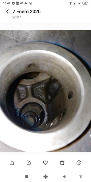
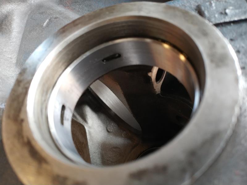
capelo (12/9/2019)
Can this be a problem? 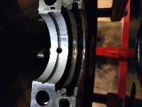
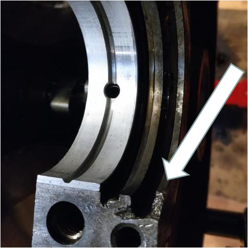
If you are referring to the chip in the edge of the block behind the groove for the rear seal, it’s a potential problem. If the chip is only on that one side, then install the seal on that side so it’s 3/8” above the main cap parting line to get some extra support from the rear seal retainer. Some extra sealer at that point is not going to hurt either.
|
|
By capelo - 7 Years Ago
|
Ted (12/10/2019)
capelo (12/9/2019)
Can this be a problem? If you are referring to the chip in the edge of the block behind the groove for the rear seal, it’s a potential problem. If the chip is only on that one side, then install the seal on that side so it’s 3/8” above the main cap parting line to get some extra support from the rear seal retainer. Some extra sealer at that point is not going to hurt either.
Would it be possible to fill with solder and then rectify? Or would that option be worse? Ted the seal was already set as you advise, thanks
|
|
By Ted - 7 Years Ago
|
capelo (12/10/2019)
... Would it be possible to fill with solder and then rectify? Or would that option be worse? Ted, the seal was already set as you advise, Thanks
It’s too bad that someone in the past wasn’t too careful in their handling of the block. But it is what you have to work with and I suspect that those blocks and/or engines are not just sitting everywhere in Spain.
While solder is easily formed and filed or worked so it can make the damaged part of the block look whole again, there’s not much to be said for the strength of such a repair being adequate enough to actually provide any additional support. But it’s likely better than nothing. Offsetting the neoprene rear seal when you put it in the groove so the end of it is sticking up ~3/8” (9-10mm) above the main cap seating surface on the side of the block that is chipped will allow both ends of the seal on that side to be supported in the aluminum rear seal retainer. This would have the highest probability of working without experiencing any future problems or leaks.
|
|
By capelo - 7 Years Ago
|
Ted (12/11/2019)
capelo (12/10/2019)
... Would it be possible to fill with solder and then rectify? Or would that option be worse? Ted, the seal was already set as you advise, Thanks It’s too bad that someone in the past wasn’t too careful in their handling of the block. But it is what you have to work with and I suspect that those blocks and/or engines are not just sitting everywhere in Spain. While solder is easily formed and filed or worked so it can make the damaged part of the block look whole again, there’s not much to be said for the strength of such a repair being adequate enough to actually provide any additional support. But it’s likely better than nothing. Offsetting the neoprene rear seal when you put it in the groove so the end of it is sticking up ~3/8” (9-10mm) above the main cap seating surface on the side of the block that is chipped will allow both ends of the seal on that side to be supported in the aluminum rear seal retainer. This would have the highest probability of working without experiencing any future problems or leaks.
as he says finding a new block here is almost impossible, I will work on filling to match that part and I will assemble the seal as indicated, thanks
|
|
By capelo - 7 Years Ago
|
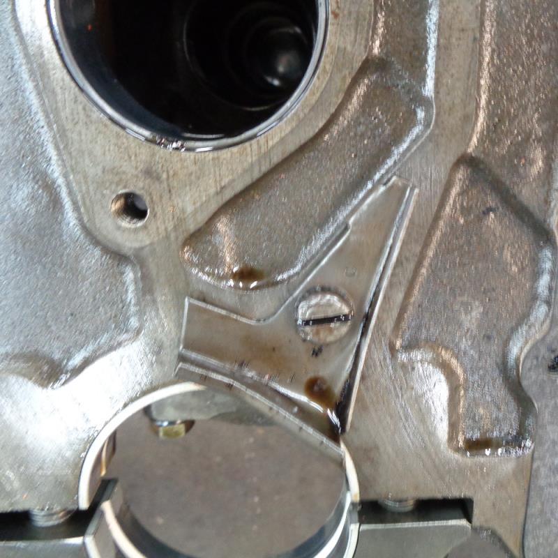
Is this necessary or just an extra?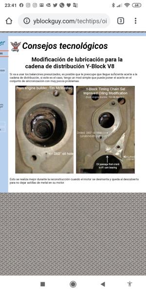
|
|
By capelo - 7 Years Ago
|
|
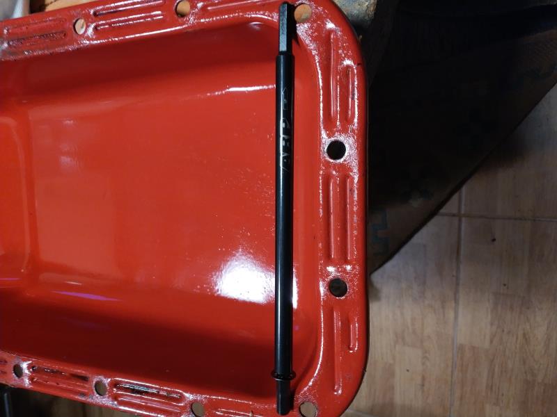
How large are the bolts that cover the pressure line of the block?
|
|
By capelo - 7 Years Ago
|
it seems that that cover was badly mounted, rubbed with the camshaft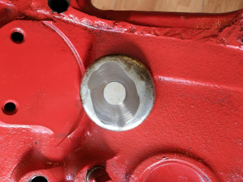
|
|
By Ted - 7 Years Ago
|
capelo (12/15/2019)
Is this necessary or just an extra?
It’s an extra. That modification allows for extra oil for the timing chain for those engines that do not have the oil trough mounted on the front of the block
capelo (12/15/2019)
How large are the bolts that cover the pressure line of the block?
¼” NPT for the oil galley plugs at the oil filter side of the block.
|
|
By Florida_Phil - 7 Years Ago
|
If you can figure out how to ship it, I have a nice standard 272 block you can have for free.
|
|
By capelo - 7 Years Ago
|
Ted (12/16/2019)
capelo (12/15/2019)
Is this necessary or just an extra? It’s an extra. That modification allows for extra oil for the timing chain for those engines that do not have the oil trough mounted on the front of the blockcapelo (12/15/2019)
How large are the bolts that cover the pressure line of the block? ¼” NPT for the oil galley plugs at the oil filter side of the block.
thank you very much Ted, I take note of it👍
|
|
By capelo - 7 Years Ago
|
Florida_Phil (12/16/2019)
If you can figure out how to ship it, I have a nice standard 272 block you can have for free.
Thank you very much for the offer, how to bring it would not have it, the problem is that it is too high a cost 👍
|
|
By Florida_Phil - 7 Years Ago
|
I don't suppose it would fit in your suitcase?  capelo (12/16/2019)
Florida_Phil (12/16/2019)
If you can figure out how to ship it, I have a nice standard 272 block you can have for free. Thank you very much for the offer, how to bring it would not have it, the problem is that it is too high a cost 👍
|
|
By capelo - 7 Years Ago
|
Florida_Phil (12/16/2019)
I don't suppose it would fit in your suitcase? capelo (12/16/2019)
Florida_Phil (12/16/2019)
If you can figure out how to ship it, I have a nice standard 272 block you can have for free. Thank you very much for the offer, how to bring it would not have it, the problem is that it is too high a cost 👍
🤔🤔Nos 😂👍
|
|
By capelo - 7 Years Ago
|
Hi guys, I am changing the bolts of the cranks for some ARP 154-6005, the case is that I have placed a pair but now I am not able to assemble the other part the bolts at the ends are more closed, I think it is due to the space what's in the crescent of the head of the bolts, but I don't know whether to lower the bolts or work on the connecting rods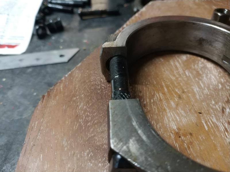 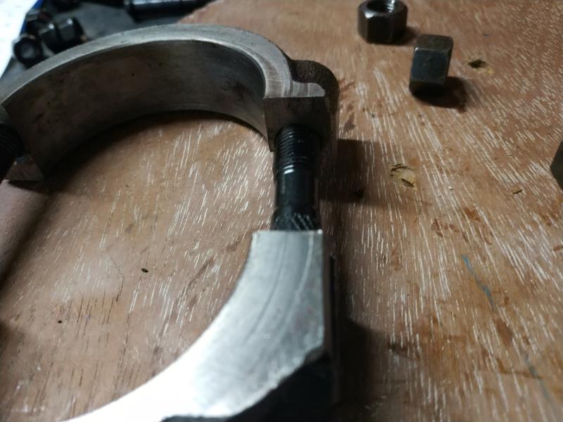
|
|
By Ted - 7 Years Ago
|
|
capelo (12/20/2019)
Hi guys, I am changing the bolts of the cranks for some ARP 154-6005, the case is that I have placed a pair but now I am not able to assemble the other part the bolts at the ends are more closed, I think it is due to the space what's in the crescent of the head of the bolts, but I don't know whether to lower the bolts or work on the connecting rods.
It’s not unusual to have to dress the ARP rod bolt heads some on a belt sander so that the bolt heads fit cleanly in the spot faced location on the rods themselves. Also keep in mind that whenever the rod bolts are removed and reinstalled in the rods, the rod ‘big ends’ do need to be resized. When using rod bolts that have knurled shanks, those bolts will find a new center each time they are installed which is why the resizing is required. If you don’t have the honing equipment for resizing the rod big ends, that resizing will need to be performed by a shop familiar with that operation. I’ll also add that if replacing the wrist pin bushings, the new bushings must be ‘swedged’ into the small end holes of the rods before any honing takes place. The swedging operation pushes the bushing material into the existing grooves in the rod so the bushing will not come loose and slip later.
|
|
By capelo - 7 Years Ago
|
Ted (12/20/2019)
capelo (12/20/2019)
Hi guys, I am changing the bolts of the cranks for some ARP 154-6005, the case is that I have placed a pair but now I am not able to assemble the other part the bolts at the ends are more closed, I think it is due to the space what's in the crescent of the head of the bolts, but I don't know whether to lower the bolts or work on the connecting rods.It’s not unusual to have to dress the ARP rod bolt heads some on a belt sander so that the bolt heads fit cleanly in the spot faced location on the rods themselves. Also keep in mind that whenever the rod bolts are removed and reinstalled in the rods, the rod ‘big ends’ do need to be resized. When using rod bolts that have knurled shanks, those bolts will find a new center each time they are installed which is why the resizing is required. If you don’t have the honing equipment for resizing the rod big ends, that resizing will need to be performed by a shop familiar with that operation. I’ll also add that if replacing the wrist pin bushings, the new bushings must be ‘swedged’ into the small end holes of the rods before any honing takes place. The swedging operation pushes the bushing material into the existing grooves in the rod so the bushing will not come loose and slip later.
thanks ted. the rectification of the end I leave when I take everything else to the machine, as well as how to remove and insert the new bushes of the wrist pin, which by the way the new ones are clevite and do not bring any greasing hole, you have to perform one after assembly? Returning to the ARP bolts can I grind them all I have inserted or would it be convenient to leave them also to those of the machine?
|
|
By Ted - 7 Years Ago
|
capelo (12/21/2019)
Thanks Ted. The rectification of the end I leave when I take everything else to the machine, as well as how to remove and insert the new bushes of the wrist pin, which by the way the new ones are clevite and do not bring any greasing hole, you have to perform one after assembly? Returning to the ARP bolts can I grind them all I have inserted or would it be convenient to leave them also to those of the machine?
Let the machinist deal with any ARP bolt modifications if they are required. Just forewarn the machine shop or machinist that there may be an issue with the head of the bolt not fitting properly in the spot faced hole in the rod. Do not install the rod bolts prior to taking them to the machine shop. The machinist will be the one installing the rod bolts as both the rods and the caps must be machined at their flat mating surfaces prior to the actual honing operation to restore the big end hole sizing.
My preference for wrist pin bushings are those that do not have the holes pre-drilled in them. Those non-drilled bushing do ‘swedge’ much nicer in the rods after installing them as having the hole already in the bushings upsets that operation. After the bushings are installed in the rods and 'swedged', then the holes are drilled just prior to the bushings being finish honed to the correct size. Be sure your machine shop has the proper equipment to 'swedge' the bushings into the rods.
|
|
By capelo - 7 Years Ago
|
Ted (12/22/2019)
capelo (12/21/2019)
Thanks Ted. The rectification of the end I leave when I take everything else to the machine, as well as how to remove and insert the new bushes of the wrist pin, which by the way the new ones are clevite and do not bring any greasing hole, you have to perform one after assembly? Returning to the ARP bolts can I grind them all I have inserted or would it be convenient to leave them also to those of the machine? Let the machinist deal with any ARP bolt modifications if they are required. Just forewarn the machine shop or machinist that there may be an issue with the head of the bolt not fitting properly in the spot faced hole in the rod. Do not install the rod bolts prior to taking them to the machine shop. The machinist will be the one installing the rod bolts as both the rods and the caps must be machined at their flat mating surfaces prior to the actual honing operation to restore the big end hole sizing. My preference for wrist pin bushings are those that do not have the holes pre-drilled in them. Those non-drilled bushing do ‘swedge’ much nicer in the rods after installing them as having the hole already in the bushings upsets that operation. After the bushings are installed in the rods and 'swedged', then the holes are drilled just prior to the bushings being finish honed to the correct size. Be sure your machine shop has the proper equipment to 'swedge' the bushings into the rods.
ok I take note thank you, what is the original size of the holes of the large ends of the rods?
|
|
By capelo - 7 Years Ago
|
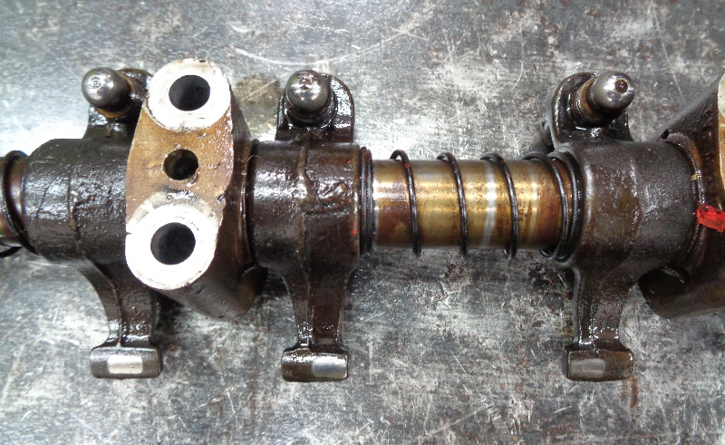
Checking the rocker trees, I have noticed that in one of them it has three different rockers aesthetically are thicker and with another reference it has something similar to this: EAB 6564-B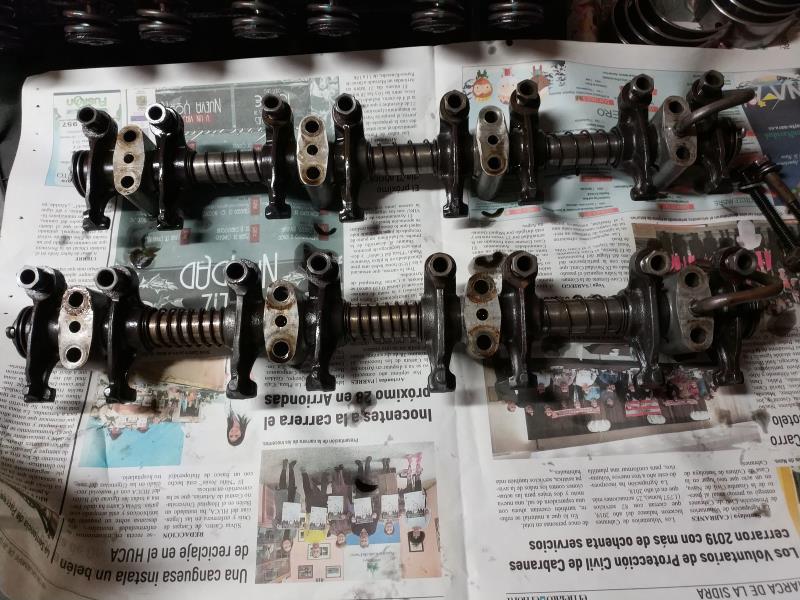 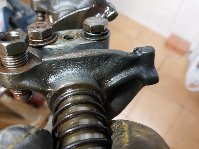 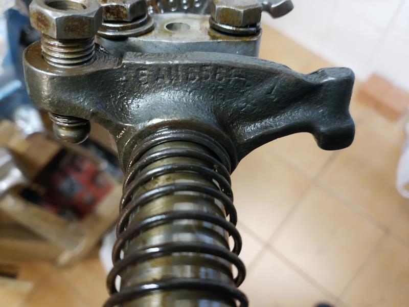
|
|
By Ted - 7 Years Ago
|
capelo (12/22/2019)
...what is the original size of the holes of the large ends of the rods?
2.3124” +/- 0.0004"
|
|
By capelo - 7 Years Ago
|
|
Today I went through the rectification workshop, I took the rods and I tried to explain the resizing of the rods after changing the bolts but they have not understood, they say that if they do that I need larger caps internally (I don't know if that exists) any image, video or explanation to understand? I am in neutral with this. You would also need the original crankshaft measurements. thanks
|
|
By KULTULZ - 7 Years Ago
|
I am watching (and learning) on the sidelines -
This post is not meant to interfere with the discussion between the OP and TED in any way.
What we are saying is that the ARP bolt has a head with small integral washer that skews the actual bolt shank off to one side and that the area on the rod @ the bolt head has to be relieved to allow the ARP bolt to center correctly within the rod to accept the rod cap correctly?
I wonder why we (at the least myself) have not heard of this before? Would that area on the rod be different between a 292 and 312 rod?
|
|
By Ted - 7 Years Ago
|
|
KULTULZ (12/23/2019)
I am watching (and learning) on the sidelines -
This post is not meant to interfere with the discussion between the OP and TED in any way.
What we are saying is that the ARP bolt has a head with small integral washer that skews the actual bolt shank off to one side and that the area on the rod @ the bolt head has to be relieved to allow the ARP bolt to center correctly within the rod to accept the rod cap correctly?
I wonder why we (at the least myself) have not heard of this before? Would that area on the rod be different between a 292 and 312 rod?
When using the ARP 154-6004 rod bolts in the ECZ, C1TE, and C2AE rods, I don’t experience much issue with rod bolt fitment in those rods. The EBU rods do require a longer bolt and that’s where the ARP 154-6005 rod bolt set comes into play. It’s when using the ARP 154-6005 bolts in the EBU rods that I occasionally must lightly grind on the exterior part of the rod bolt heads so they properly seat in the spot faced recess in the rod. The head design between the 6004 and 6005 rod bolt sets is different which explains to some degree why there is a fitment problem.
This likely hasn’t been brought up as most ‘do it yourself’ engine assemblers send their connecting rods out to be reconditioned. Those shops doing the rod resizing performs the bolt head modifications as a standard practice so it’s not even mentioned. I’ve come across the rod bolt fitment issues in other engines also so it’s not just a Y problem. I’ve been doing this long enough that it seems second nature. I did come close to going into a tyrade on this subject but I'll just trudge forward and leave it alone.
|
|
By Ted - 7 Years Ago
|
|
capelo (12/22/2019)
Checking the rocker trees, I have noticed that in one of them it has three different rockers aesthetically are thicker and with another reference it has something similar to this: EAB 6564-B
I’m assuming you are talking about the pads on the ends of the rockers varying in width. Closely examine the undersides or wear portions of those pads and make sure that the valve stem are making a full contact with the rocker pad. If they are making a full contact, then no problem exists. In the event that the rockers with narrower pads are contacting the valve stems at the outer edge of the pad and not making a full contact, then move those rockers to valve locations that will center the valve stem on the rocker pad. Making note of where the wear patterns are before disassembling the rockers from the shaft will help to facilitate where to move them to if required.
Here’s a picture showing how the valve stem placement can vary on the rocker arm tip. This is by design and is why the tips are designed to be as wide as they are.
|
|
By Ted - 7 Years Ago
|
capelo (12/23/2019)
Today I went through the rectification workshop, I took the rods and I tried to explain the resizing of the rods after changing the bolts but they have not understood, they say that if they do that I need larger caps internally (I don't know if that exists) any image, video or explanation to understand? I am in neutral with this. You would also need the original crankshaft measurements. thanks
In the normal course of the engine running, the rod bearing hole in the rod can become elongated over time and this will necessitate making the big end connecting rod bearing hole smaller again so it can be brought back to the proper size for the bearing to fit within it. Also keep in mind that any time the rod bolts are removed from the rods, the potential is there for the cap to no longer align with the connecting rod as the rod bolts can find a new 'center' depending upon the rod bolt design. Part of the rod resizing process involves grinding 0.001”-0.003” from the flats on both the rods and the caps. This intentionally makes the rod bearing hole in the rod undersized so it can be honed back to both the factory specification and also become a ‘true’ hole once more. Some shops will only take material off of the caps but by the book and doing the job properly will require both the caps and the rods being resurfaced at their flats.
It was interesting in looking for a video of this as there is a lot of misinformation and wrong ways in which to do the rod resizing operation. I was happy with this particular video in regards to the big end resizing. Ford full floated connecting rods do require the new bushings to be swedged into place before honing and that was not displayed in this particular video.
https://www.youtube.com/watch?v=lzUa8kYLSRU
|
|
By KULTULZ - 7 Years Ago
|
TED, I want to personally THANK YOU for your time and interest and sharing secrets here.
I am 71 and still learning ... 
|
|
By capelo - 7 Years Ago
|
Ted (12/24/2019)
capelo (12/22/2019)
Checking the rocker trees, I have noticed that in one of them it has three different rockers aesthetically are thicker and with another reference it has something similar to this: EAB 6564-BI’m assuming you are talking about the pads on the ends of the rockers varying in width. Closely examine the undersides or wear portions of those pads and make sure that the valve stem are making a full contact with the rocker pad. If they are making a full contact, then no problem exists. In the event that the rockers with narrower pads are contacting the valve stems at the outer edge of the pad and not making a full contact, then move those rockers to valve locations that will center the valve stem on the rocker pad. Making note of where the wear patterns are before disassembling the rockers from the shaft will help to facilitate where to move them to if required. Here’s a picture showing how the valve stem placement can vary on the rocker arm tip. This is by design and is why the tips are designed to be as wide as they are.
Thanks for the comments, my question is not about the contact on the head of the valve, what I see different is the rocker itself, that its constitution is thicker and the reference also, can be seen in the photos, the doubt is that is not of a different ratio
|
|
By capelo - 7 Years Ago
|
Ted (12/24/2019)
capelo (12/23/2019)
Today I went through the rectification workshop, I took the rods and I tried to explain the resizing of the rods after changing the bolts but they have not understood, they say that if they do that I need larger caps internally (I don't know if that exists) any image, video or explanation to understand? I am in neutral with this. You would also need the original crankshaft measurements. thanks In the normal course of the engine running, the rod bearing hole in the rod can become elongated over time and this will necessitate making the big end connecting rod bearing hole smaller again so it can be brought back to the proper size for the bearing to fit within it. Also keep in mind that any time the rod bolts are removed from the rods, the potential is there for the cap to no longer align with the connecting rod as the rod bolts can find a new 'center' depending upon the rod bolt design. Part of the rod resizing process involves grinding 0.001”-0.003” from the flats on both the rods and the caps. This intentionally makes the rod bearing hole in the rod undersized so it can be honed back to both the factory specification and also become a ‘true’ hole once more. Some shops will only take material off of the caps but by the book and doing the job properly will require both the caps and the rods being resurfaced at their flats. It was interesting in looking for a video of this as there is a lot of misinformation and wrong ways in which to do the rod resizing operation. I was happy with this particular video in regards to the big end resizing. Ford full floated connecting rods do require the new bushings to be swedged into place before honing and that was not displayed in this particular video. https://www.youtube.com/watch?v=lzUa8kYLSRU
Thanks👍
|
|
By Joe-JDC - 7 Years Ago
|
|
There are some things in a refurbish that I have always considered mandatory to be replaced, such as the timing gears and chain, rocker shafts and arms, and valve guides, springs, seals, crankshaft and rod bearings. I know it is difficult for you being in Spain, but I would encourage you to try to buy a new set of rocker arms and shafts for your engine if you intend to use it on a daily basis for some years to come. If it is a pleasure vehicle, then replacing the mismatched parts at a minimum. 16 new rocker arms should not be a job stopper. Joe-JDC
|
|
By KULTULZ - 7 Years Ago
|
Are you saying the actual rockers arms appear to have different lengths? They do to me also, but it may be the angle of the photo shot. EAN-6564-B ID's as 1954-55 1.43 ration ... ??? ....
EDIT -
The word should read ratio. It must have been close to mess call to have posted ration ...
Some appear longer. They appear to be staggered (in length) as to INTAKE-EXHAUST. They also have later 1956/ one piece adjusting screws.
|
|
By capelo - 7 Years Ago
|
Joe-JDC (12/24/2019)
There are some things in a refurbish that I have always considered mandatory to be replaced, such as the timing gears and chain, rocker shafts and arms, and valve guides, springs, seals, crankshaft and rod bearings. I know it is difficult for you being in Spain, but I would encourage you to try to buy a new set of rocker arms and shafts for your engine if you intend to use it on a daily basis for some years to come. If it is a pleasure vehicle, then replacing the mismatched parts at a minimum. 16 new rocker arms should not be a job stopper. Joe-JDC
thanks if that reference claims to be 1.43, then although aesthetically different signal that is correct, the axles I have to replace fixed, it will not be a daily use vehicle but if it will be used every week, stuck in this and already spent about 3000 dollars Sometimes I think of changing some other things, such as rockers or rods, but between distance and not knowing which part is compatible, it sometimes makes me go back. What rockers are sold online? and rods?
|
|
By Tedster - 7 Years Ago
|
The rocker arm shafts are readily available.
The rocker arms, are somewhat difficult to find. At least, at what I consider a reasonable cost. Normally $25 each. I spent some time on eBay and pieced together 16 N.O.S. for around $4 to $5 each, that is a price I thought was reasonable. It took a while to round them up, one or two or three at a time. Loose rocker arms on rocker shafts will be erratic in their operation and will also "leak" excessive oil pressure.
An alternative is to send the existing rocker arms for re-sleeving or rebushing the bores, though this can be somewhat expensive from your location. Look for complete rocker arm pair assemblies on eBay or similar - these were either service replacements or something made up, but will include all new hardware for (relatively) a good price. Maybe $250 to $300 or so.
Also recommend new valve springs of appropriate "installed height", ordinarily setup with .010", .015" or .030" hardened shims.
|
|
By KULTULZ - 7 Years Ago
|
|
What rockers are sold online? and rods?
Rocker Arms - http://www.rockerarms.com/pages/about.html
Years ago, you could buy exchange rods as well as crankshaft kits. I don't know if they are still offered. TED will know.
|
|
By capelo - 7 Years Ago
|
|
Thanks for the answers, on the rods I will wait for you to tell me about the grinding workshop, on the rocker arms is there a set of rollers at a good price? If I had to look for some new rods I would have to search for a source configuration? If someone can give me the measurements of an original crankshaft? Thank you
|
|
By stuey - 7 Years Ago
|
Hi there
http://www.ford-y-block.com/dimensions.htm
http://www.ford-y-block.com/enginepa.htm
http://www.ford-y-block.com/valvetrain.htm
The above may be of interest.
Shipping plus import taxes are a killer.
stuey
UK
|
|
By Ted - 7 Years Ago
|
capelo (12/25/2019)
... If someone can give me the measurements of an original crankshaft? Thank you
The standard journal specs for the 292 crankshafts are as follows.
Mains – 2.4984” ±0.0004”
Rods – 2.1884” ±0.0004”
It’s always recommended to install the bearings in their respective bores and then check those I.D. dimensions to insure that the oil clearance values will be in the ball park. My preference is to take those installed bearing dimensions and then grind the crankshaft accordingly for the desired oil clearance. Checking all the bearing thicknesses with a ball micrometer also helps to insure that all the bearings are indeed the same. The crankshaft can be ground either smaller or bigger than spec to get the desired clearance and that’s simply due to the different variances working against you. When the various component dimensions vary to the extreme positive or extreme negative, bearing clearances can be either too tight or too loose if relying simply on the standard based values. Bearing thicknesses due to manufacturing variances are the major culprit here when the machine work is within specs.
|
|
By darrell - 7 Years Ago
|
|
i find new rockers to pricey for me.i have lots of sets around and take them apart until i find good shafts check the rockers for fit reface them and away to go.i always knock the plugs out and clean the shafts out.i had trouble finding the plugs last time.
|
|
By capelo - 7 Years Ago
|
Thanks for the links, I already knew the page of mummerte, but I have been unable to contact to make an order. Living here is much more expensive for the postage I have imposed 👍
|
|
By capelo - 7 Years Ago
|
Ted (12/26/2019)
capelo (12/25/2019)
... If someone can give me the measurements of an original crankshaft? Thank you The standard journal specs for the 292 crankshafts are as follows. Mains – 2.4984” ±0.0004” Rods – 2.1884” ±0.0004” It’s always recommended to install the bearings in their respective bores and then check those I.D. dimensions to insure that the oil clearance values will be in the ball park. My preference is to take those installed bearing dimensions and then grind the crankshaft accordingly for the desired oil clearance. Checking all the bearing thicknesses with a ball micrometer also helps to insure that all the bearings are indeed the same. The crankshaft can be ground either smaller or bigger than spec to get the desired clearance and that’s simply due to the different variances working against you. When the various component dimensions vary to the extreme positive or extreme negative, bearing clearances can be either too tight or too loose if relying simply on the standard based values. Bearing thicknesses due to manufacturing variances are the major culprit here when the machine work is within specs.
thanks i take note
|
|
By capelo - 7 Years Ago
|
Opinión
https://www.sekotimsale.com/ford-5566-292ci48l-connecting-rod-p-300662.htm
|
|
By KULTULZ - 7 Years Ago
|
Those are reman conn rods. They will be exchange meaning they will want the old rods.
You posted your current rods are at a local machine shop now?
|
|
By capelo - 7 Years Ago
|
KULTULZ (12/27/2019)
Those are reman conn rods. They will be exchange meaning they will want the old rods. You posted your current rods are at a local machine shop now?
it seems that they don't ask for some in return, that was an option, in case the problem is not solved in the rectification workshop
|
|
By capelo - 7 Years Ago
|
at what diameter did this hole pierce? it is now 0.060"
|
|
By Ted - 6 Years Ago
|
|
That hole sizing is fine but don’t go any larger than that. The oil flow can be further reduced by the size of groove you put in the back of the cam thrust plate.
|
|
By capelo - 6 Years Ago
|
Ted (1/1/2020)
That hole sizing is fine but don’t go any larger than that. The oil flow can be further reduced by the size of groove you put in the back of the cam thrust plate.
Ok thanks
|
|
By capelo - 6 Years Ago
|
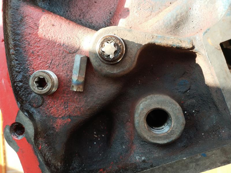
I'm having trouble removing these two plugs, any suggestions? thanks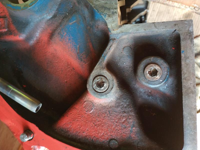
|
|
By NoShortcuts - 6 Years Ago
|
Capelo. From John Mummert's web site, topic 'Y-BLOCK TECHNICAL INFORMATION', under 'Y-Block assembly errors' . . .
Oil gallery plugs. Remove all oil plugs and the oil filter adapter before having your block hot tanked. I’ve had the best luck by drilling out the center of the oil plug, leaving the hex. After heating the plugs with a torch they come right out. I have never damaged a block using this method.
Hope this helps!
|
|
By capelo - 6 Years Ago
|
NoShortcuts (1/5/2020)
Capelo. From John Mummert's web site, topic 'Y-BLOCK TECHNICAL INFORMATION', under 'Y-Block assembly errors' . . .Oil gallery plugs. Remove all oil plugs and the oil filter adapter before having your block hot tanked. I’ve had the best luck by drilling out the center of the oil plug, leaving the hex. After heating the plugs with a torch they come right out. I have never damaged a block using this method. Hope this helps!
thanks torch I have already used but without results, I missed the head of the cap is round, I have to try to drill ...
|
|
By capelo - 6 Years Ago
|
after a good fight got 👍
|
|
By Ted - 6 Years Ago
|
Good to see you got that threaded plug out. They can be problematic at times.
While heating the plug and dripping beeswax on the threads seems to be the accepted way to remove those, I just haven’t had much luck doing it that way. I end up having to drill a hole in the plug and use a square style broken screw extractor to remove those plugs. I like to run taps in all the threaded holes before vatting to insure that the threads are clean and undamaged.
|
|
By paul2748 - 6 Years Ago
|
Another way of moving stubborn plugs or broken bolts is to weld a nut on it.
|
|
By capelo - 6 Years Ago
|
Ted (1/6/2020)
Good to see you got that threaded plug out. They can be problematic at times. While heating the plug and dripping beeswax on the threads seems to be the accepted way to remove those, I just haven’t had much luck doing it that way. I end up having to drill a hole in the plug and use a square style broken screw extractor to remove those plugs. I like to run taps in all the threaded holes before vatting to insure that the threads are clean and undamaged.
I have already checked all the threads and everything is ok
|
|
By capelo - 6 Years Ago
|
paul2748 (1/7/2020)
Another way of moving stubborn plugs or broken bolts is to weld a nut on it.
that is a good solution already used on occasion 👍
|
|
By capelo - 6 Years Ago
|
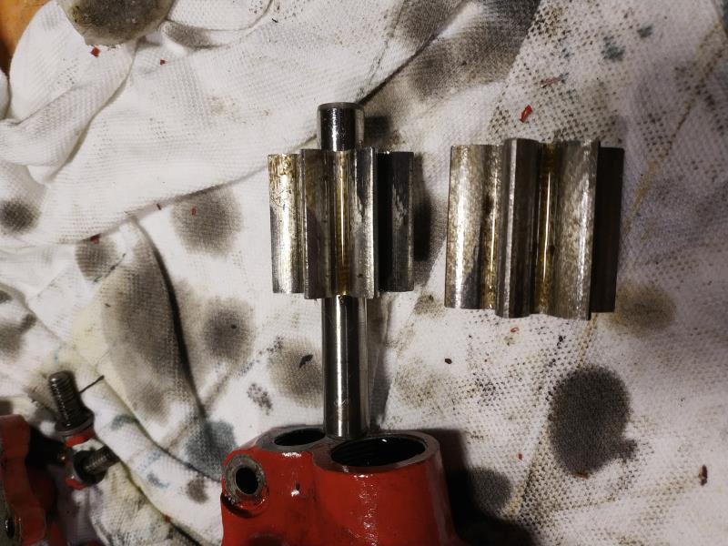
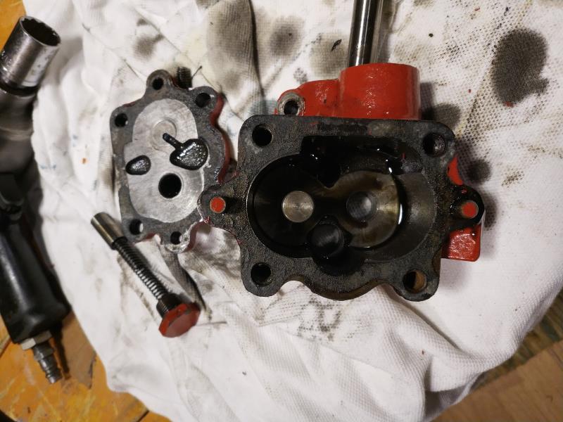
I feel very upset with this, I bought a new oil pump thinking it would be gerotor, a failure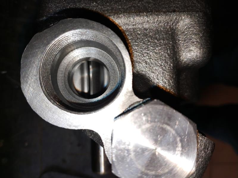 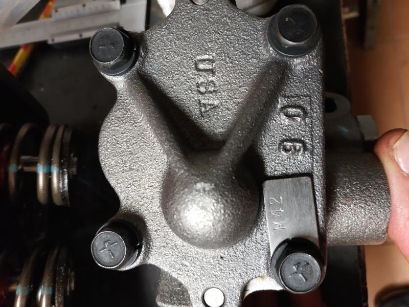
|
|
By capelo - 6 Years Ago
|
a necessary change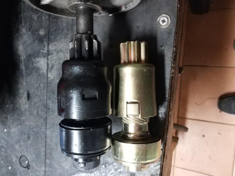
|
|
By capelo - 6 Years Ago
|
Any suggestions for installation?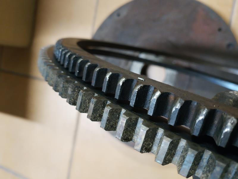 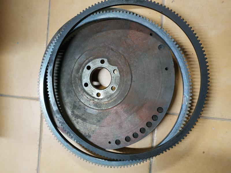
|
|
By charliemccraney - 6 Years Ago
|
|
Gerotor pumps aren't available new. Rebuild kits are available, Melling K-56, if you can find a good used one to rebuild.
|
|
By paul2748 - 6 Years Ago
|
Heat the ring gear in the oven, the other part in the freezer
capelo (1/9/2020)
Any suggestions for installation?
|
|
By paul2748 - 6 Years Ago
|
Heat the ring gear in the oven, the flywheel in the freezer
capelo (1/9/2020)
Any suggestions for installation?
|
|
By capelo - 6 Years Ago
|
charliemccraney (1/9/2020)
Gerotor pumps aren't available new. Rebuild kits are available, Melling K-56, if you can find a good used one to rebuild.
Ok thanks 👍
|
|
By capelo - 6 Years Ago
|
this serves for me 292…?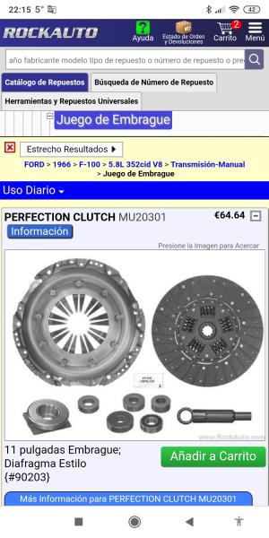
|
|
By capelo - 6 Years Ago
|
So were my valves, any opinions? How can I proceed for cleaning?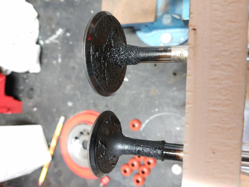 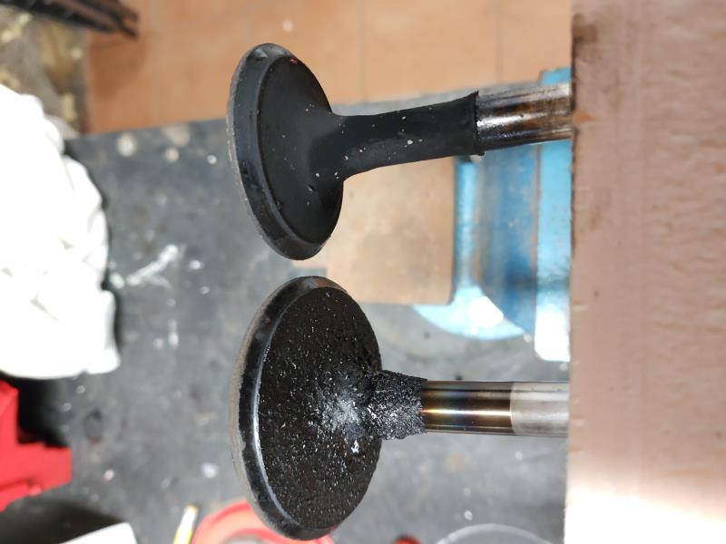 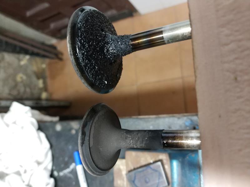 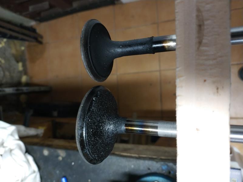
|
|
By Joe-JDC - 6 Years Ago
|
|
If you have access to a soda blaster, it will clean those valves quickly. If not, what you can do is spin them in a drill press and use a wire brush in an electric hand drill to clean the carbon. Others have soaked them in carburetor cleaner and used scotch brite pads, or you can carefully spin them with a drill and use a 100 grit crocus cloth to remove the carbon. I have seen some folks use a bench grinder with a wire wheel and wear leather gloves to hold the valves and rotate them to remove the carbon. Many options, if you have any of these things available there. Joe-JDC
|
|
By carl - 6 Years Ago
|
|
Oven cleaner will clean the carbon off of the valves Carl
|
|
By capelo - 6 Years Ago
|
Joe-JDC (1/11/2020)
If you have access to a soda blaster, it will clean those valves quickly. If not, what you can do is spin them in a drill press and use a wire brush in an electric hand drill to clean the carbon. Others have soaked them in carburetor cleaner and used scotch brite pads, or you can carefully spin them with a drill and use a 100 grit crocus cloth to remove the carbon. I have seen some folks use a bench grinder with a wire wheel and wear leather gloves to hold the valves and rotate them to remove the carbon. Many options, if you have any of these things available there. Joe-JDC
thank you note I will try to acquire a blaster soda
|
|
By capelo - 6 Years Ago
|
carl (1/12/2020)
Oven cleaner will clean the carbon off of the valves Carl
I have tried it on the cameras they take a lot, but on the resistor valves, thanks
|
|
By capelo - 6 Years Ago
|
capelo (1/11/2020)
this serves for me 292…?
anyone about this?
|
|
By PF Arcand - 6 Years Ago
|
Not sure, but that clutch assembly is not listed for a Y-Block.. so ?
|
|
By paul2748 - 6 Years Ago
|
Personally, like the Centerforce clutches, the dual friction model. Find the number of splines on the trans and the diameter of the disc and go to their web site and get part numbers... Jegs or Summitt should have what you picked out.
|
|
By 2721955meteor - 6 Years Ago
|
|
what or where is the other site,why no comments avail or able to view. seems every time i go to this site things change with no prior info. are only selected members allowed coment now??
|
|
By capelo - 6 Years Ago
|
|
I asked for a change from lever style to diaphragm style
|
|
By Ted - 6 Years Ago
|
2721955meteor (1/15/2020)
What or where is the other site, why no comments avail or able to view. Seems every time I go to this site things change with no prior info. Are only selected members allowed comment now??
No changes to the YBF site. You did make a comment so that part works. I’ll suggest some routine maintenance on the computer or software on your end if you are getting inconsistent responses. Deleting cookies and temporary files is something I do on a weekly basis on my end as the computer I'm currently using just gets quirky if I don’t do that.
|
|
By Ted - 6 Years Ago
|
capelo (1/15/2020)
I asked for a change from lever style to diaphragm style
The diaphragm pressure plate will work in lieu of not locating a new ‘Long’ style (3 finger) pressure plate. You do need to insure that whatever you order is for a 1 3/8” ten spline input shaft and has an eleven inch clutch disk.
|
|
By capelo - 6 Years Ago
|
Ted (1/15/2020)
capelo (1/15/2020)
I asked for a change from lever style to diaphragm style The diaphragm pressure plate will work in lieu of not locating a new ‘Long’ style (3 finger) pressure plate. You do need to insure that whatever you order is for a 1 3/8” ten spline input shaft and has an eleven inch clutch disk.
I'm going to look for a new clutch disc and stay with the long lever, thanks
|
|
By capelo - 6 Years Ago
|
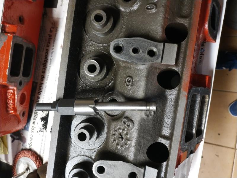
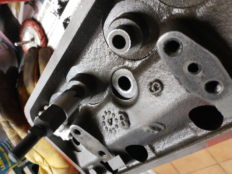
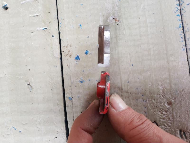
today I was modifying the heads to place positive style valve seals, I modified a tool for drilling sheet metal for it, I put images
|
|
By Ted - 6 Years Ago
|
|
Be sure to check the retainer to valve seal clearance. You’ll want at least 0.060” more than whatever your net valve lift is expected to be.
|
|
By capelo - 6 Years Ago
|
In case anyone is interested, I think I have found a replacement for the rocker adjustment screws, everything matches but I do not know how long they are, this is the one referred to (GRANE 99689-16)
https://www.summitracing.com/parts/crn-99680-16/
|
|
By capelo - 6 Years Ago
|
Ted (1/19/2020)
Be sure to check the retainer to valve seal clearance. You’ll want at least 0.060” more than whatever your net valve lift is expected to be.
how can I know the net travel of the valve to make measurements
|
|
By capelo - 6 Years Ago
|
Ted (1/19/2020)
Be sure to check the retainer to valve seal clearance. You’ll want at least 0.060” more than whatever your net valve lift is expected to be.
now there is a distance of 0.492 "
|
|
By Ted - 6 Years Ago
|
capelo (1/19/2020)
Ted (1/19/2020)
Be sure to check the retainer to valve seal clearance. You’ll want at least 0.060” more than whatever your net valve lift is expected to be. how can I know the net travel of the valve to make measurements
The math for calculating the minimum required distance is as follows:
Lobe lift multipled by the rocker ratio plus 0.060” minus the valve lash.
In your case: 0.320” X 1.43 + 0.060” – 0.020” = 0.498” minimum
If going with 1.6:1 rockers then: 0.320” X 1.6 + 0.060” – 0.020” = 0.552” minimum
More than minimum is always desirable.
|
|
By capelo - 6 Years Ago
|
Ted (1/21/2020)
capelo (1/19/2020)
Ted (1/19/2020)
Be sure to check the retainer to valve seal clearance. You’ll want at least 0.060” more than whatever your net valve lift is expected to be. how can I know the net travel of the valve to make measurements The math for calculating the minimum required distance is as follows: Lobe lift multipled by the rocker ratio plus 0.060” minus the valve lash. In your case: 0.320” X 1.43 + 0.060” – 0.020” = 0.498” minimum If going with 1.6:1 rockers then: 0.320” X 1.6 + 0.060” – 0.020” = 0.552” minimum More than minimum is always desirable.
Thanks Ted, good explanation, I will try to go to the maximum possible space
|
|
By capelo - 6 Years Ago
|
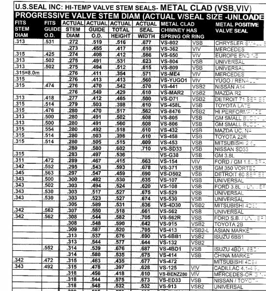
After adapting the valve guides, I am looking for new seals, they have to be 11/32 "x 0.500". Any suggestions for this?
I have these two visits:
ENGINETECH S2926
QUALCAST 3881045
|
|
By Ted - 6 Years Ago
|
For positive type valve seals, I use U.S.Seals Inc. For the 11/32” X 0.500” applications the part number is VS107V.
https://ussealparts.com/catalogsearch/result/?q=vs107v
|
|
By capelo - 6 Years Ago
|
Thanks Ted 👍
|
|
By capelo - 6 Years Ago
|
|
I screwed up, I hadn't measured accurately enough, it should be 11/32 "x 0.510". I'm sorry
|
|
By capelo - 6 Years Ago
|
|
I only see .500 "-.502" -. 530 ", could anyone fit in?
|
|
By Ted - 6 Years Ago
|
The VS107V seal is rubber lined on its inside and doing a rough measurement with a dial caliper on my end indicates that it may work on the 0.510” diameter guide. This may just require some oil on the guide and seal surfaces to help the seal slide in place. Here’s a picture of the seal dimensions page from the U.S. Seal catalog which may help you make a more informed decision if you want to use the #107 seal or possibly another.
|
|
By capelo - 6 Years Ago
|
Ted (1/27/2020)
The VS107V seal is rubber lined on its inside and doing a rough measurement with a dial caliper on my end indicates that it may work on the 0.510” diameter guide. This may just require some oil on the guide and seal surfaces to help the seal slide in place. Here’s a picture of the seal dimensions page from the U.S. Seal catalog which may help you make a more informed decision if you want to use the #107 seal or possibly another.
Ted thanks for the information, I'm going to order a VS-107V game. I can have them in oil some time before. Looking at U.S. SEAL, I have seen this other seal, I can order both and see what happens.
https://ussealparts.com/vs-vo3v.html
|
|
By capelo - 6 Years Ago
|
Following Ted's advice, I have manufactured a new fixing piece for the distributor
|
|
By capelo - 6 Years Ago
|
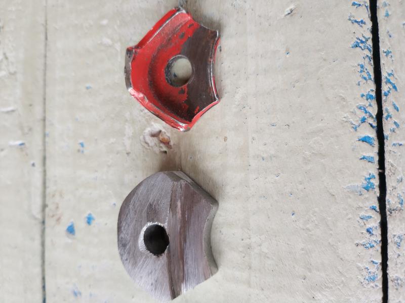
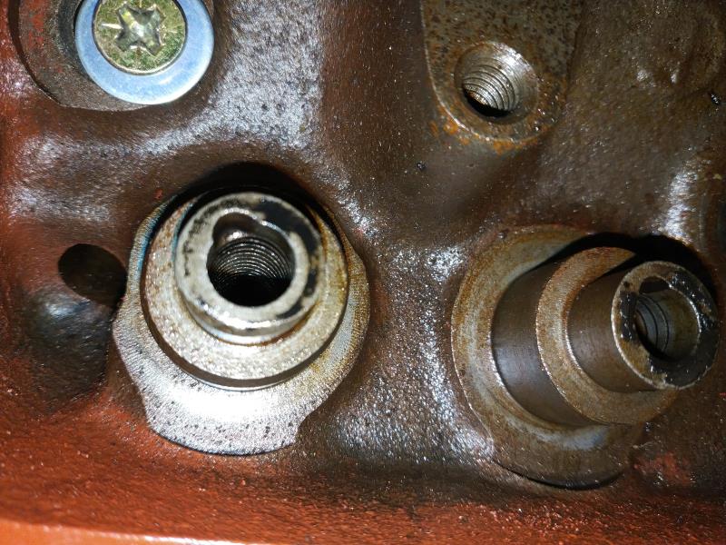
I've seen these guides in some heads
|
|
By NoShortcuts - 6 Years Ago
|
One of the procedures that can be utilized to restore the clearance of the valve stems in worn valve guides is called knurling. This might account for the continuous groove that you see on the inside bore of the valve guides pictured.
I'm not familiar with the half round opening that has been machined in the end of the valve guides pictured. They may have been added using a two or four lip straight end or ball end mill cutter. I'm speculating that their intent is to serve as a shallow reservoir for capturing a small amount of engine oil from the rocker arm assemblies to assure some engine oil lubrication to the valve guide and valve stem. Again, I have not seen these half round openings utilized before with the knurling process. John (Hoosier Hurricane), Ted Eaton or other Forum members may have a better handle on this.
Valve guide knurling is an alternative to using replacement valves with oversize stems, installing replacement guides, or machining the existing worn guides to permit installing bronze sleeves in the valve guide bores.
Hope this helps.
|
|
By Hoosier Hurricane - 6 Years Ago
|
|
Charlie, one of the better quality knurling outfits uses a guide rod with an exposed hardened roller that protrudes above the surface of the guide rod. There is a drill ;guide included in the kit that is slipped into the guide and a standard drill bit is used to machine the notch you noticed at the top of the guide. The knurling tool is then inserted in the guide with the roller indexed into the notch and is powered with an electric drill to gently roll the guide material so that the guide can be reamed to fit. The notch allows the knurling roller to start, the roller is set at a slight angle in the tool so that it "screws" itself down the guide. I used one of those kits when I worked in a NAPA machine shop years ago.
|
|
By capelo - 6 Years Ago
|
|
thanks guys for the clarifications 👍
|
|
By NoShortcuts - 6 Years Ago
|
Hoosier Hurricane (2/3/2020)
Charlie, one of the better quality knurling outfits uses a guide rod with an exposed hardened roller that protrudes above the surface of the guide rod. There is a drill ;guide included in the kit that is slipped into the guide and a standard drill bit is used to machine the notch you noticed at the top of the guide. The knurling tool is then inserted in the guide with the roller indexed into the notch and is powered with an electric drill to gently roll the guide material so that the guide can be reamed to fit. The notch allows the knurling roller to start, the roller is set at a slight angle in the tool so that it "screws" itself down the guide. I used one of those kits when I worked in a NAPA machine shop years ago.
Hoosier Hurricane. Thanks, John. I appreciate your description and explanation. It sounds like a time consuming process if all the valve guides needed to be knurled to return them to tolerance.
Charlie
|
|
By capelo - 6 Years Ago
|
today the new rocker adjusters have arrived, they look good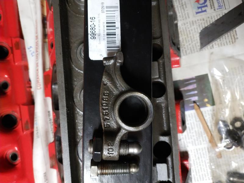 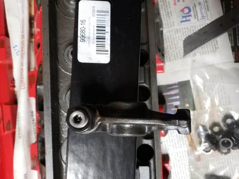
|
|
By capelo - 6 Years Ago
|
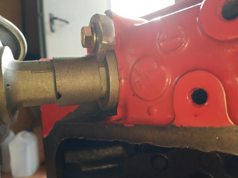
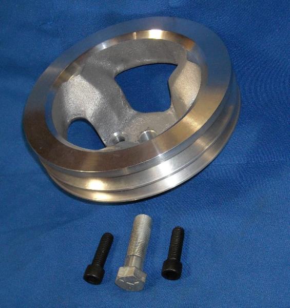
I am manufacturing a pulley for the power steering pump, any comments or advice is welcome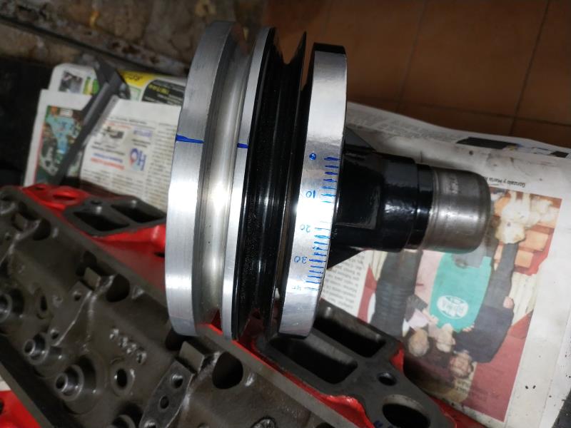 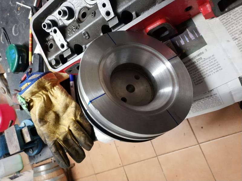 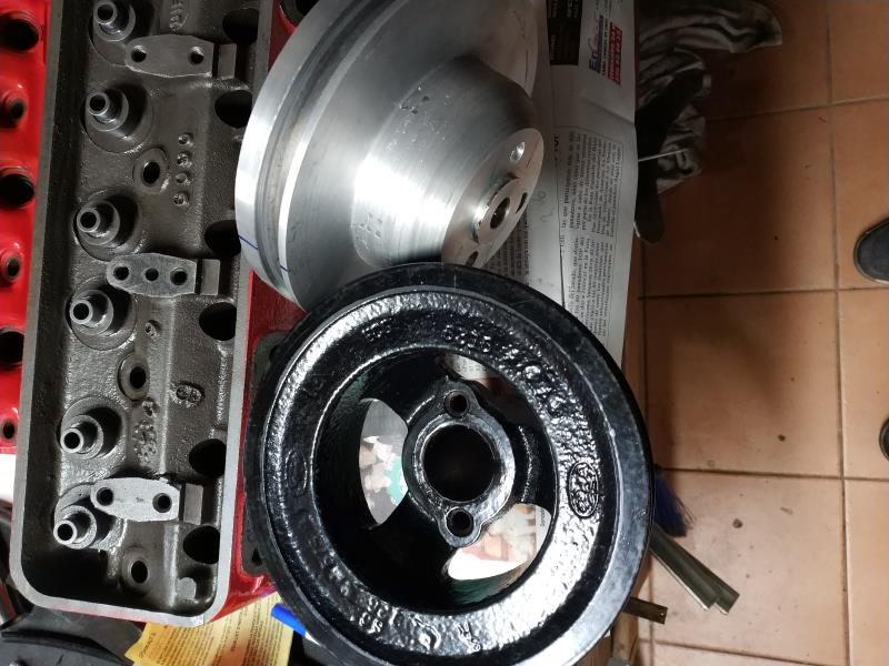
|
|
By FORD DEARBORN - 6 Years Ago
|
Copelo, it's very difficult for me to determine with my eyesight but that isn't aluminum, is it? If it's steel and you left a small gap between the two pulleys to allow for some flexing and sxpansion, then I think it should work OK. Nice machine work, JEFF.................
|
|
By capelo - 6 Years Ago
|
FORD DEARBORN (2/4/2020)
Copelo, it's very difficult for me to determine with my eyesight but that isn't aluminum, is it? If it's steel and you left a small gap between the two pulleys to allow for some flexing and sxpansion, then I think it should work OK. Nice machine work, JEFF.................
Thank you, yes it is aluminum
|
|
By FORD DEARBORN - 6 Years Ago
|
I am not an expert in metallurgy by any stretch but IMHO some issues could creep in between this application of 2 very different metals. Aluminum will yield much more than steel when compressed and not return completely to it's original shape when cooled. AL also has a much greater thermal expansion rate than steel. Being "worked" under the heads of the 2 bolts and many thermal cycles it may eventually "work" loose. There also will be a lot of compression under the crankshaft bolt. I hope others will comment but these are my thoughts on this very dynamic highly stressed part. Stressed by heat, mechanical motion and harmonics. JEFF.....................
|
|
By capelo - 6 Years Ago
|
FORD DEARBORN (2/4/2020)
I am not an expert in metallurgy by any stretch but IMHO some issues could creep in between this application of 2 very different metals. Aluminum will yield much more than steel when compressed and not return completely to it's original shape when cooled. AL also has a much greater thermal expansion rate than steel. Being "worked" under the heads of the 2 bolts and many thermal cycles it may eventually "work" loose. There also will be a lot of compression under the crankshaft bolt. I hope others will comment but these are my thoughts on this very dynamic highly stressed part. Stressed by heat, mechanical motion and harmonics. JEFF.....................
I had noticed the one that sells me, yours is made of cast aluminum.
|
|
By FORD DEARBORN - 6 Years Ago
|
Sometimes I tend to over think the issue. I didn't realize the aftermarket add-on is aluminum. Looks like you will be fine and again, nice machine work, I may have spent too much time in the aviation field. JEFF........
|
|
By capelo - 6 Years Ago
|
FORD DEARBORN (2/4/2020)
Sometimes I tend to over think the issue. I didn't realize the aftermarket add-on is aluminum. Looks like you will be fine and again, nice machine work, I may have spent too much time in the aviation field. JEFF........
😀👍
|
|
By capelo - 6 Years Ago
|
|
My concern now is about the possible excessive weight and how far I could lighten without destroying it.
|
|
By capelo - 6 Years Ago
|
I have another question, I have seen the sale of aluminum thermostat housing that says fit in a 292, does anyone know or know any for sale apart from that of mummerte?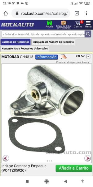
|
|
By capelo - 6 Years Ago
|
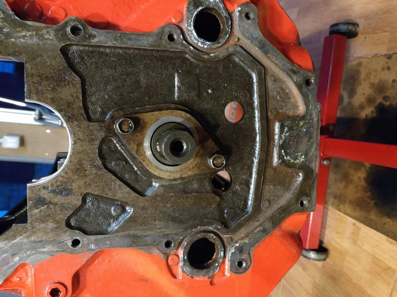
I have also seen in several images of "Y" engines that carry what they call oil deflector inside the distribution housing, my engine did not have it, is it important?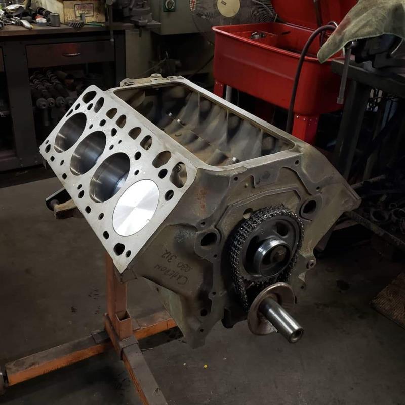
|
|
By NoShortcuts - 6 Years Ago
|
Capelo. An oil deflector inside the (ignition) distributor housing? OR are you referring to an oil deflector inside the timing chain cover used for the first 3 years of y-block production that was intended to deflect oil onto the crankshaft gear?
- The rocker arm shaft on the oil pump side of the engine block, has an overflow tube that is intended to direct oil toward the ignition distributor gear that is driven by the camshaft gear.
- The rocker arm shaft on the opposite side of the engine oil pump, has an overflow tube that directs oil toward the engine's timing chain and the crankshaft and camshaft gears.
Please clarify what we're talking about.
|
|
By capelo - 6 Years Ago
|
NoShortcuts (2/6/2020)
Capelo. An oil deflector inside the (ignition) distributor housing? OR are you referring to an oil deflector inside the timing chain cover used for the first 3 years of y-block production that was intended to deflect oil onto the crankshaft gear? - The rocker arm shaft on the oil pump side of the engine block, has an overflow tube that is intended to direct oil toward the ignition distributor gear that is driven by the camshaft gear. - The rocker arm shaft on the opposite side of the engine oil pump, has an overflow tube that directs oil toward the engine's timing chain and the crankshaft and camshaft gears. Please clarify what we're talking about.
I want to refer to the one in the crankshaft in front of the distribution chain, thanks
|
|
By 57RancheroJim - 6 Years Ago
|
I think he is referring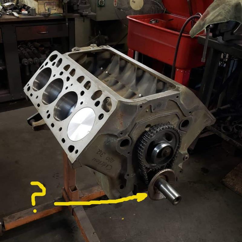 to the oil slinger to the oil slinger
|
|
By NoShortcuts - 6 Years Ago
|
Capelo. As Ted indicated, the oil trough was only used on FoMoCo y-block engines in the U.S. during production years 1954, '55, and '56.
Like the camshaft counterweight that was originally employed, and the rockerarm shaft sheet metal oil baffle trays (intended to deflect excess oil away from the valve stem umbrella seals), the engineers were likely pressured by the cost analyzers and determined that these measures were not necessary. So, in production years 1957 - 1964, these items were removed.
As a hobbyist, I add each of these items to the y-blocks engines I put together for myself or with fellow hobbyists.
Don't lose any sleep in putting your engine together if your engine does not include these items. If all of your clearances, tolerances, and assembly procedures are correct, your engine will give you reliable service and dependability.
Enjoy the fruit of your efforts!
|
|
By Ted - 6 Years Ago
|
capelo (2/5/2020)
I have another question, I have seen the sale of aluminum thermostat housing that says fit in a 292, does anyone know or know any for sale apart from that of mummerte?
The pictured thermostat housing looks to be for a 360/360 FE Ford engine. If the description says it’s for a 292 Ford, then the picture could be wrong or the seller missed the application in the description altogether.
|
|
By Ted - 6 Years Ago
|
capelo (2/5/2020)
I have also seen in several images of "Y" engines that carry what they call oil deflector inside the distribution housing, my engine did not have it, is it important?
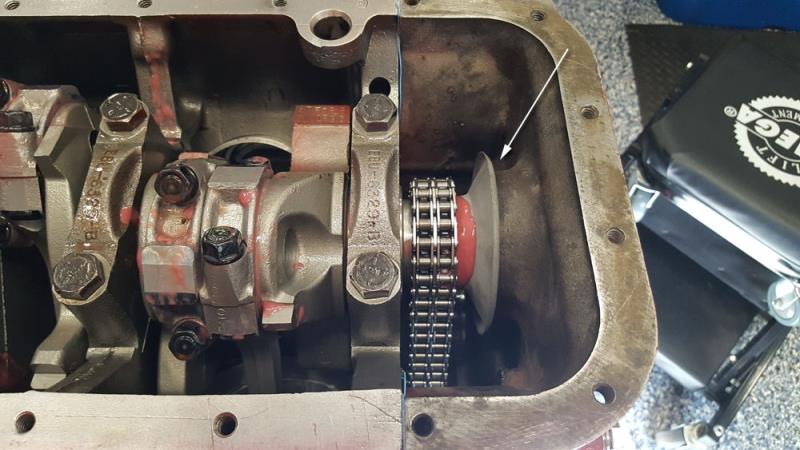
That oil deflector located in front of the timing gear on the crankshaft snout came on all years of Ford Y’s. It’s there to prevent the oil from splashing directly on the front timing cover seal which minimizes oil leaks in that area.
|
|
By Florida_Phil - 6 Years Ago
|
When I assembled my current engine, I had what I thought was an issue with this deflector. I used a double roller timing chain and the deflector rubbed the inside of the front cover. After the balancer was installed the clearance was adequate. The balancer holds this deflector in position. The pink stuff in this photo is assembly lube.
|
|
By capelo - 6 Years Ago
|
|
thanks guys for your comments, can those baffles be achieved or would it be possible to manufacture? or just leave it without him? Any single image of the baffle
|
|
By capelo - 6 Years Ago
|
On the housing of thermostat I will consult with the seller if there is a mistake in the image, when placing an aluminum intake I would like to have it also in aluminum
https://www.rockauto.com/es/catalog/ford,1962,f-100,4.8l+292cid+v8,1335428,cooling+system,thermostat+housing+/+water+outlet,10337
|
|
By Ted - 6 Years Ago
|
capelo (2/7/2020)
thanks guys for your comments, can those baffles be achieved or would it be possible to manufacture? or just leave it without him? Any single image of the baffle
While that crankshaft oil slinger (baffle or deflector by other names) could be fabricated, it would be a challenge with the number of bends that are involved.
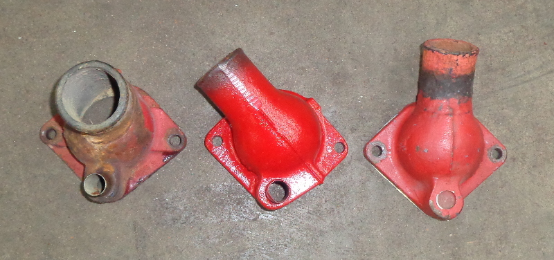
The standard replacement thermostat housings for the Ford Y will be cast iron. John Mummert does offer the thermostat housing in aluminum. Be aware that there are three styles of thermostat housings available with one being for the passenger cars, one for the ’55-’57 Thunderbirds, and one for the Ford pickups and trucks. I’ll post a picture later of the three most common oem thermostat housings as the hose sizes and positioning of the coolant outlet does varies on each.
|
|
By capelo - 6 Years Ago
|
Ted, today I received the valve seals and some caps, from US SEAL. Thank you for showing me that store, great prices and very fast shipping 👍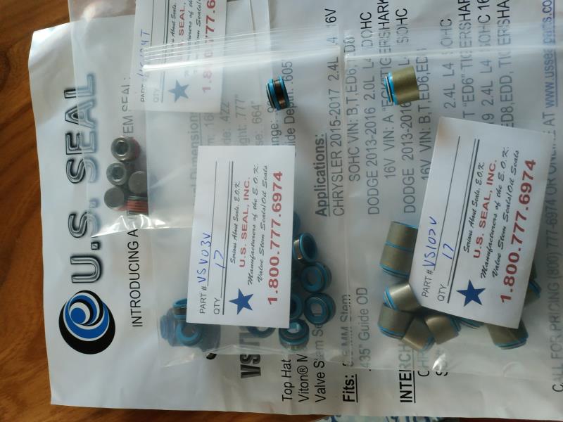 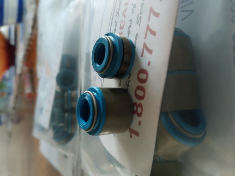
|
|
By Ted - 6 Years Ago
|
Here is a picture showing the three basic styles of thermostat housings for the Ford Y. From left to right, 1955-1957 Thunderbird, 1954-1962 Ford and Mercury car, 1954-1964 pickup and truck. The 1954 models used a ½” bypass hose while a 5/8” bypass hose was incorporated on the housings starting in 1955.
|
|
By capelo - 6 Years Ago
|
Ted, thanks for the information, I think I'll have to settle for my old reconditioned thermostat housing, I can't access the one from mummerte from here,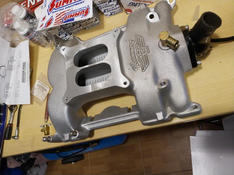 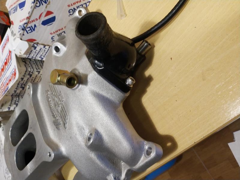
|
|
By capelo - 6 Years Ago
|
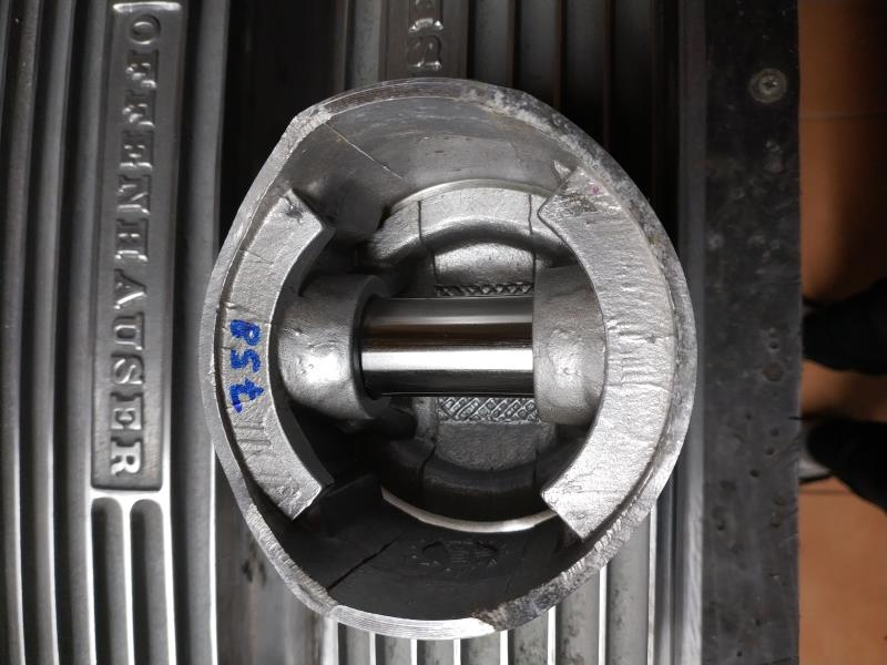
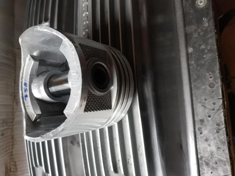
While I have the engine material in the machine shop, I wanted to advance some work, I would like to balance everything possible and I want to start with the pistons, I have thought them and they are between 757 and 759gr, the scale only needs one gram, tomorrow they bring me one of 0.01gr, the case is that I do not know if it is a great imbalance and if it is where I have to act to match weights
|
|
By Ted - 6 Years Ago
|
|
If you get all the various parts within ½ gram or less, you’ll be good to go. Getting it as close to zero that you can is always the target though. Be sure to include the wrist pin with the piston to help minimize weight stack ups on the various parts. That will require keeping the wrist pins with their respective pistons which is recommended anyhow depending upon how they were pin fitted at the manufacturer.
|
|
By capelo - 6 Years Ago
|
Ted (2/11/2020)
If you get all the various parts within ½ gram or less, you’ll be good to go. Getting it as close to zero that you can is always the target though. Be sure to include the wrist pin with the piston to help minimize weight stack ups on the various parts. That will require keeping the wrist pins with their respective pistons which is recommended anyhow depending upon how they were pin fitted at the manufacturer.
thanks Ted, seeing the images where I can act to match the weights? Can I polish the part of the skirt where the number?
|
|
By Ted - 6 Years Ago
|
The design and construction of the piston will determine where the best areas of the piston are for any weight reductions that must be performed. With that said, then the type of tools or machinery that’s available will dictate how the weight is removed. In your case, a lathe or milling machine can be used to machine the cast lips below the wrist pin on the inner edge of the skirt. A milling machine equipped with a long end mill or cutter can be used to catch the thick portion behind the ring lands but care must be taken to not make anything so thin as to weaken or damage the piston.
While I’m not a big advocate of using a drill for weight reduction in the pistons, it can be used if used prudently. Although not recommended as a normal weight reduction operation for pistons, drill bits are often used by the uninformed to remove weight in the deck portion of the piston and that can create stress risers there. Nothing says you can’t use a drill on that lip on the bottom and inner portion of the piston. You have to be careful in not going too deep with the drill. Doing a multitude of shallow indentations with the drill bit will be much better strength wise than doing a fewer number of deeper holes. Because you are only working with removing only two grams on some of the pistons, overall weight reduction is not going to be a major deal.
|
|
By capelo - 6 Years Ago
|
Ted (2/13/2020)
The design and construction of the piston will determine where the best areas of the piston are for any weight reductions that must be performed. With that said, then the type of tools or machinery that’s available will dictate how the weight is removed. In your case, a lathe or milling machine can be used to machine the cast lips below the wrist pin on the inner edge of the skirt. A milling machine equipped with a long end mill or cutter can be used to catch the thick portion behind the ring lands but care must be taken to not make anything so thin as to weaken or damage the piston. While I’m not a big advocate of using a drill for weight reduction in the pistons, it can be used if used prudently. Although not recommended as a normal weight reduction operation for pistons, drill bits are often used by the uninformed to remove weight in the deck portion of the piston and that can create stress risers there. Nothing says you can’t use a drill on that lip on the bottom and inner portion of the piston. You have to be careful in not going too deep with the drill. Doing a multitude of shallow indentations with the drill bit will be much better strength wise than doing a fewer number of deeper holes. Because you are only working with removing only two grams on some of the pistons, overall weight reduction is not going to be a major deal.
thanks Ted for the explanation, apart from the areas you have indicated, can I work on the surfaces that I indicate with the arrows?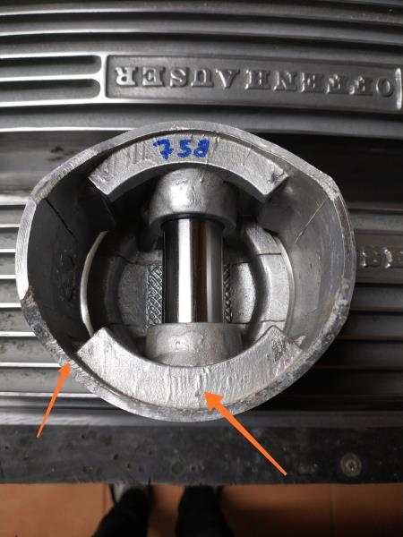
|
|
By capelo - 6 Years Ago
|
I have already brought the heads of the machine, I have to give it a good wash and start assembling, any advice?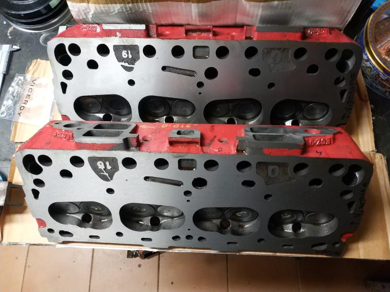 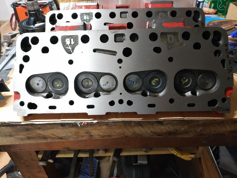
|
|
By capelo - 6 Years Ago
|
hello I have put the camshaft bushings and I have some doubt, first how hard it has to turn the camshaft once inside, with the pinion of the distribution set and with the hand it turns but I do not know the appropriate resistance. on the bushings, the one on the back of the engine when I put it does not match the two holes in the block, which I can do there
|
|
By capelo - 6 Years Ago
|
I have seen this to relieve space, what do you think?
|
|
By Ted - 6 Years Ago
|
In regards to the picture asking where to take the material off of the piston for weight matching purposes, concentrate only on the inner lip. Keep away from the skirt or outer portion of the piston.
On that rear cam bearing where both holes do not align with the holes in the block, you will need to modify the bearing so that the hole for the distributor shaft is open to the bearing.
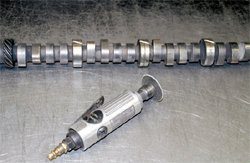
On your ‘old’ camshaft with the added grooves, you only need one or two of the journals with a ‘cutting’ groove. My preference is to only groove the second from last journal when making a cutting tool for the bearings. If it’s a front or rear cam bearing that needs some material removed, then I’ll cut a groove in the end cam journal of the ‘tool’ I’m using or just use a bearing knife to cut the bearing manually. Having the cut itself diagonal as you show in your picture is good as it increases the cutting area as well as allowing the bearing material to clean itself from the groove in the ‘tool’ much easier. Also when adding the groove to the old camshaft, cut it at an angle or not perpendicular to the journal surface so you have a sharp cutting edge when turning only in one direction. This allows the ‘tool’ to be installed turning it opposite of the cutting direction so it can be placed at the appropriate bearing without necessarily cutting on bearings that may not need any material removed from them.
Before doing any cutting on the cam bearings, put the new camshaft in the block from the front and rear using the respective journals on the camshaft. Assuming those fit and turn fine, this points to the tightness of your camshaft then being on one of the center three cam bearings. Then take the camshaft and work it in the two journals from both the front and rear. If the camshaft still turns freely doing this, then the center cam bearing is suspect but this does not rule out a crooked cam tunnel. I typically don’t see crooked cam tunnels on the 272/292 engines but there’s a first time for everything. I would come closer to seeing a cam bearing that’s installed slightly crooked or ‘cocked’ but an undersize hole in the block can also make fitment tighter than normal.
|
|
By capelo - 6 Years Ago
|
Ted (2/15/2020)
In regards to the picture asking where to take the material off of the piston for weight matching purposes, concentrate only on the inner lip. Keep away from the skirt or outer portion of the piston. On that rear cam bearing where both holes do not align with the holes in the block, you will need to modify the bearing so that the hole for the distributor shaft is open to the bearing. On your ‘old’ camshaft with the added grooves, you only need one or two of the journals with a ‘cutting’ groove. My preference is to only groove the second from last journal when making a cutting tool for the bearings. If it’s a front or rear cam bearing that needs some material removed, then I’ll cut a groove in the end cam journal of the ‘tool’ I’m using or just use a bearing knife to cut the bearing manually. Having the cut itself diagonal as you show in your picture is good as it increases the cutting area as well as allowing the bearing material to clean itself from the groove in the ‘tool’ much easier. Also when adding the groove to the old camshaft, cut it at an angle or not perpendicular to the journal surface so you have a sharp cutting edge when turning only in one direction. This allows the ‘tool’ to be installed turning it opposite of the cutting direction so it can be placed at the appropriate bearing without necessarily cutting on bearings that may not need any material removed from them. Before doing any cutting on the cam bearings, put the new camshaft in the block from the front and rear using the respective journals on the camshaft. Assuming those fit and turn fine, this points to the tightness of your camshaft then being on one of the center three cam bearings. Then take the camshaft and work it in the two journals from both the front and rear. If the camshaft still turns freely doing this, then the center cam bearing is suspect but this does not rule out a crooked cam tunnel. I typically don’t see crooked cam tunnels on the 272/292 engines but there’s a first time for everything. I would come closer to seeing a cam bearing that’s installed slightly crooked or ‘cocked’ but an undersize hole in the block can also make fitment tighter than normal.
Ok, I'll make those checks before making the cuts. On the rear bearing I am in fact able to take it out, make a new hole and reinsert. On the pistons I will focus on the Waves indicated by you. Thank you
|
|
By capelo - 6 Years Ago
|
well I have already solved the two problems, I have drilled the bearing and repositioned, now it aligns with the two holes. I did the tests with the camshaft and I could see that the problem was the first bearing, from the rear it turned well inside four of five bearings, so with the old cutout cam until it had space, it was tight in the last third of said bearing, thanks for the tips, I keep going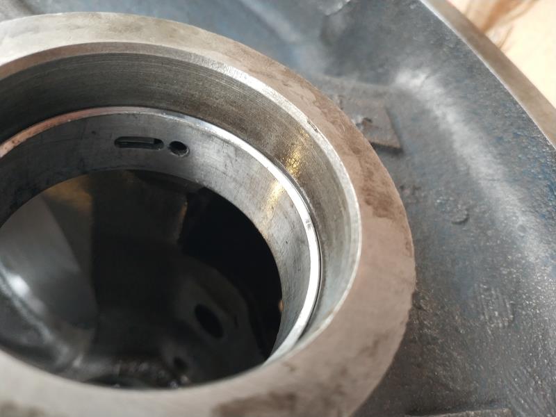 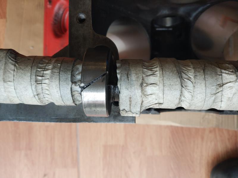
|
|
By 1946international - 6 Years Ago
|
|
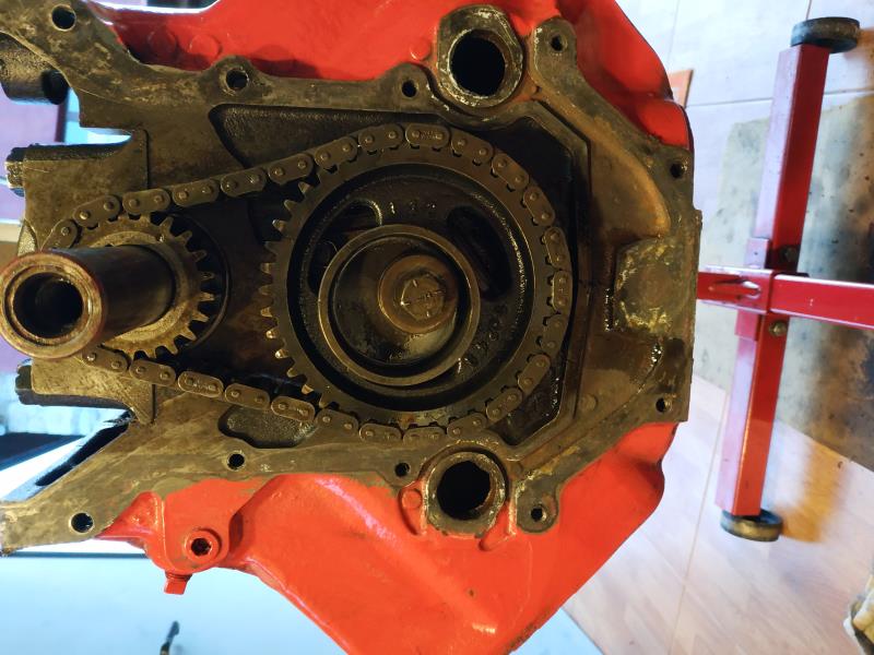
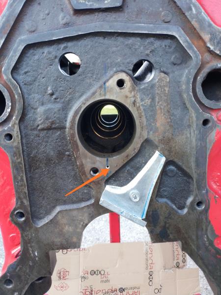
This is a photo that the OP had posted many pages ago, what is the silver trough thing? not the oil hole with the arrow pointing to it, but the silver item that looks like it is made of sheet metal and is attached with the one phillips screw/bolt ?
|
|
By Rudder2fly - 6 Years Ago
|
|
Oil trough for timing chain with oil coming from the lifter galley.
|
|
By 1946international - 6 Years Ago
|
|
is that a stock part? I have never seen one.
|
|
By Ted - 6 Years Ago
|
The timing chain oil troughs were factory installed on the 1954-1956 Ford Y’s. I have come across a few 1957 engines with them but by the end of 1956 they were being phased out as a cost cutting measure. Here’s another picture of the oil trough.
|
|
By capelo - 6 Years Ago
|
I see that you have already clarified the question about the extra greasing of the distribution chain.
We keep moving forward, I have to reassemble the rocker shaft, I have new rocker shafts, the rocker arm tips have been rectified and new adjustment screws are going to be mounted.
Apart from being careful with the alignment of the grease holes, any other advice? The rockers are all supposed to be the same can be grouped together or do I have to check anything?
|
|
By capelo - 6 Years Ago
|
today has touched a little decoration.
|
|
By capelo - 6 Years Ago
|
|
What clearance does the harmonic damper have on the crankshaft shaft? I tried mine and I think it has too much.
|
|
By capelo - 6 Years Ago
|
capelo (2/23/2020)
What clearance does the harmonic damper have on the crankshaft shaft? I tried mine and I think it has too much.
any comments?
|
|
By Ted - 6 Years Ago
|
capelo (2/23/2020)
What clearance does the harmonic damper have on the crankshaft shaft? I tried mine and I think it has too much.
While I don’t find any crankshaft snout to damper clearance specs in the service manual, I look for the two dimensions to be reasonably close to each other without being an interference fit. My personal limit for the damper hole would be no more than 0.002” larger than the snout. A 0.0005” interference fit would make the damper tough to install and remove.
|
|
By capelo - 6 Years Ago
|
Ted (2/27/2020)
capelo (2/23/2020)
What clearance does the harmonic damper have on the crankshaft shaft? I tried mine and I think it has too much. While I don’t find any crankshaft snout to damper clearance specs in the service manual, I look for the two dimensions to be reasonably close to each other without being an interference fit. My personal limit for the damper hole would be no more than 0.002” larger than the snout. A 0.0005” interference fit would make the damper tough to install and remove.
Well, I think I have a problem, here there is more slack than I said, I will try to put a small video, but I think I have a slack of about 0.03 "
|
|
By capelo - 6 Years Ago
|
|
I can't publish a video
|
|
By Hoosier Hurricane - 6 Years Ago
|
|
Where are you measuring the bore of the pulley? The pulleys are counter bored oversize for a short distance on the inboard end. Measure your bore on the outboard (front) end of the pulley hub. I think you'll find a better fit there. I think the overbore is to make it easier for the assembly line worker to align the key with the keyway.
|
|
By capelo - 6 Years Ago
|
Hoosier Hurricane (2/27/2020)
Where are you measuring the bore of the pulley? The pulleys are counter bored oversize for a short distance on the inboard end. Measure your bore on the outboard (front) end of the pulley hub. I think you'll find a better fit there. I think the overbore is to make it easier for the assembly line worker to align the key with the keyway.
that measurement is inside the pulley, I have not measured the outside there is more complicated, I did not know that the hole was conical, I will try to put it upside down and check the clearance, thanks
|
|
By Ted - 6 Years Ago
|
Capelo. I watched the video you sent and the video really does not give an idea exactly how loose the damper is on the shaft. Having fore and aft movement simply tells me that there is clearance between the damper and crankshaft snout but not how much. You are back to doing some real measuring to get a better feel for determining exactly how much clearance between those two parts exists. When checking the crankshaft snout, make sure you measure it in several spots along its length to insure it is uniform in measurement along its length. Likewise do the same for the damper. As John mentions, the damper does have an increase in hole size at the entry end to aid in the installation on the crankshaft. What you don’t want is ‘wibble-wobble’ on the damper once it’s installed all the way up to the lower crankshaft gear. Tightening the damper will ultimately correct for some of the looseness you are experiencing.
|
|
By capelo - 6 Years Ago
|
Ted (2/29/2020)
Capelo. I watched the video you sent and the video really does not give an idea exactly how loose the damper is on the shaft. Having fore and aft movement simply tells me that there is clearance between the damper and crankshaft snout but not how much. You are back to doing some real measuring to get a better feel for determining exactly how much clearance between those two parts exists. When checking the crankshaft snout, make sure you measure it in several spots along its length to insure it is uniform in measurement along its length. Likewise do the same for the damper. As John mentions, the damper does have an increase in hole size at the entry end to aid in the installation on the crankshaft. What you don’t want is ‘wibble-wobble’ on the damper once it’s installed all the way up to the lower crankshaft gear. Tightening the damper will ultimately correct for some of the looseness you are experiencing.
I have measured the crankshaft snout at three points, inside 1,230 "in the center 1,2299" and outside 1,2295 ". The pulley could only measure the inside with 1.25", I have no way of measuring there, I have tried to introduce the pulley upside down and it shows that it enters fairer. The slack of the video is without tightening the screw once it clears disappears when pressed against the pinion of the distribution, what catches my attention is the ease with which it enters and its margin before tightening the
|
|
By charliemccraney - 6 Years Ago
|
Short of taking it to someone with the right tools and paying them to measure it, an inside dial caliper will get a pretty accurate measurement and pretty cost effectively, as far as precision measurement devices go, particularly for smaller measurements. There are digital versions, if you prefer that.
I have one of these for about 3/8" to 1 3/8" and it's off by about .003" from end to end. I don't know if that's just the nature of all of them (error in converting angular movement to linear) or simply mine being a cheaper Chinese make. If you use a micrometer to check and adjust it for the desired measurement, it will be accurate.
Link to an example. There may be cheaper options, search for yourself:
https://www.ebay.com/itm/SPI-3-4-to-1-3-4-Inch-Inside-Dial-Caliper-Gage-0-001-Inch-Graduation-3-25-I/282535179307?hash=item41c868b42b:g:YvcAAOSwXetZSTGQ
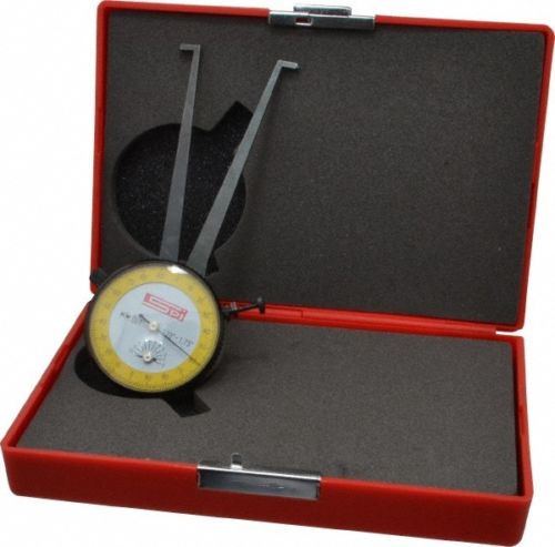
|
|
By capelo - 6 Years Ago
|
charliemccraney (2/29/2020)
Short of taking it to someone with the right tools and paying them to measure it, an inside dial caliper will get a pretty accurate measurement and pretty cost effectively, as far as precision measurement devices go, particularly for smaller measurements. There are digital versions, if you prefer that. I have one of these for about 3/8" to 1 3/8" and it's off by about .003" from end to end. I don't know if that's just the nature of all of them (error in converting angular movement to linear) or simply mine being a cheaper Chinese make. If you use a micrometer to check and adjust it for the desired measurement, it will be accurate. Link to an example. There may be cheaper options, search for yourself: https://www.ebay.com/itm/SPI-3-4-to-1-3-4-Inch-Inside-Dial-Caliper-Gage-0-001-Inch-Graduation-3-25-I/282535179307?hash=item41c868b42b:g:YvcAAOSwXetZSTGQ
Thanks for the idea, but I can't find a meter yet at a good price, it will be better to find where to take it to measure👍
|
|
By Ted - 6 Years Ago
|
Capelo. I have twelve Y crankshafts sitting here in the shop from everything for a 256 to 312 engines including a steel crank for a 292. The crankshaft snout measurements for those ranged from 1.2486” to 1.2504”. I also had four dampers laying loose here in the shop and the hole measurements not including the enlarged register that aids in starting the damper on the crankshaft ranged from 1.2490” to 1.2499”. Based on this particular set of measurements, the interference fit can be as tight as 0.0014” while the other end of the scale can have the damper as loose as 0.0013”.
Of not any consideration in regards to how tight the damper is on the shaft, the enlarged portion of the damper holes (register) ranged in measurement from 1.2685” to 1.2740”. Those enlarged registers are about 1.300” long before getting to the portion of the damper that actually dictates how tight the damper will be to the crankshaft snout.
|
|
By capelo - 6 Years Ago
|
Ted (3/3/2020)
Capelo. I have twelve Y crankshafts sitting here in the shop from everything for a 256 to 312 engines including a steel crank for a 292. The crankshaft snout measurements for those ranged from 1.2486” to 1.2504”. I also had four dampers laying loose here in the shop and the hole measurements not including the enlarged register that aids in starting the damper on the crankshaft ranged from 1.2490” to 1.2499”. Based on this particular set of measurements, the interference fit can be as tight as 0.0014” while the other end of the scale can have the damper as loose as 0.0013”. Of not any consideration in regards to how tight the damper is on the shaft, the enlarged portion of the damper holes (register) ranged in measurement from 1.2685” to 1.2740”. Those enlarged registers are about 1.300” long before getting to the portion of the damper that actually dictates how tight the damper will be to the crankshaft snout.
Thanks for the contribution, harmonic shock absorber may not be too far from these measures, but I'm still waiting to find who fashion the outside
|
|
By capelo - 6 Years Ago
|
I have finally got the rods, I tried to think them for balance, I made a tool to help it, but something does not work well because every time I try to weigh the same part gives me a different measure, any suggestions?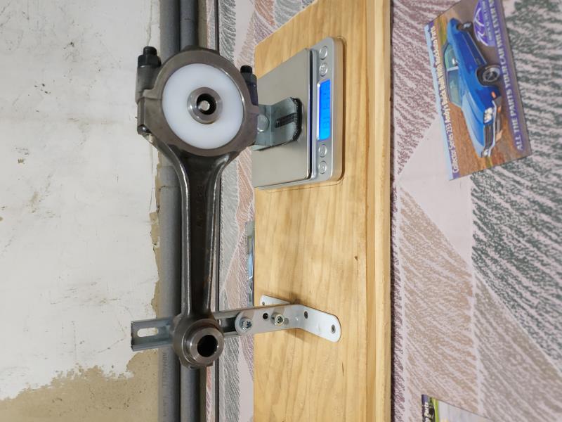
|
|
By MplsMike - 6 Years Ago
|
|
Can you place something wide across the scale, like a board or a tray, and then set the rod on that?
|
|
By Ted - 6 Years Ago
|
The non-scale end of the rod needs to free float. Letting the rod hang loose on the non-scale end will permit for a more relaxed movement of the rod end at the scale and thus more consistency in the readings.
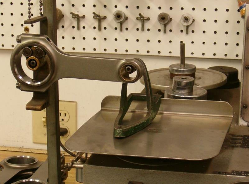
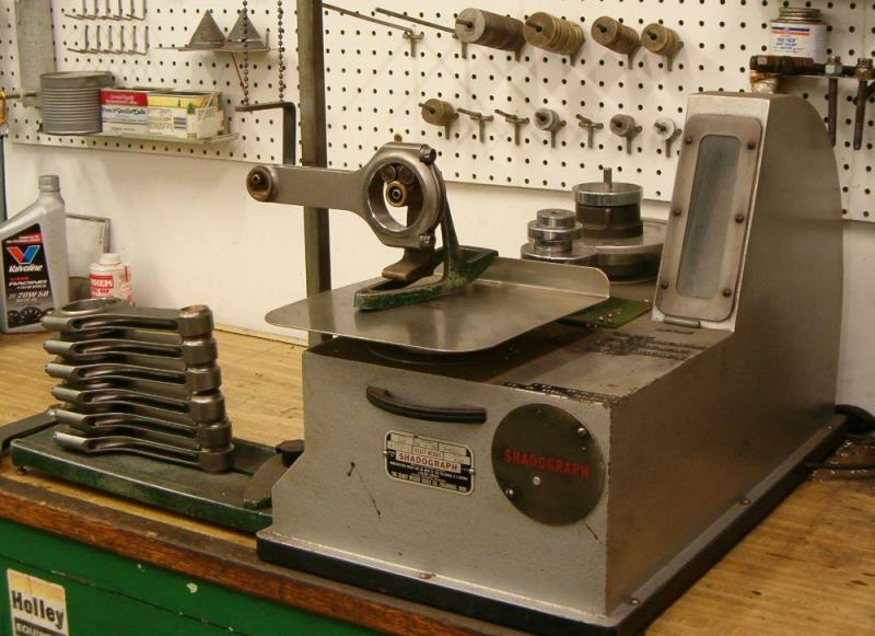
|
|
By Lord Gaga - 6 Years Ago
|
|
Friction of the wrist pin.
|
|
By capelo - 6 Years Ago
|
I have made modifications, but with the same result, the measurements are always different, I think I'm going to stop balancing the rods, is this operation necessary?
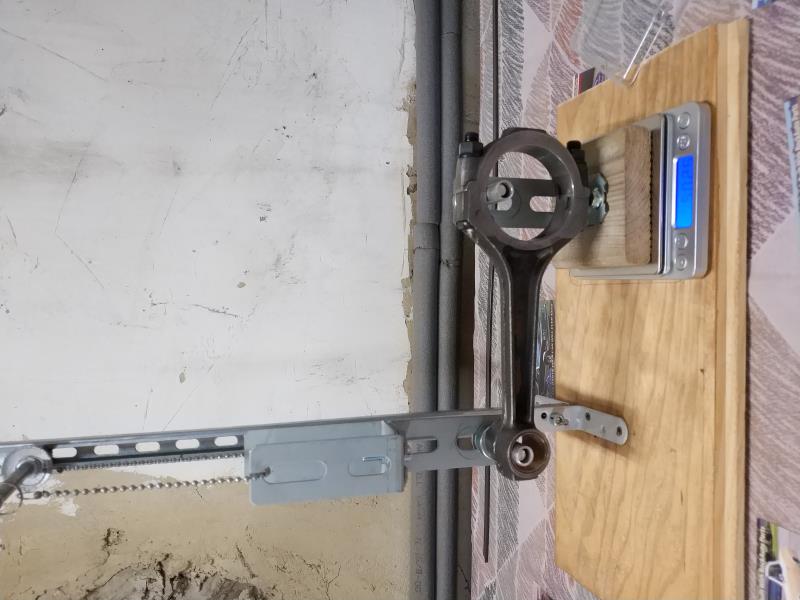 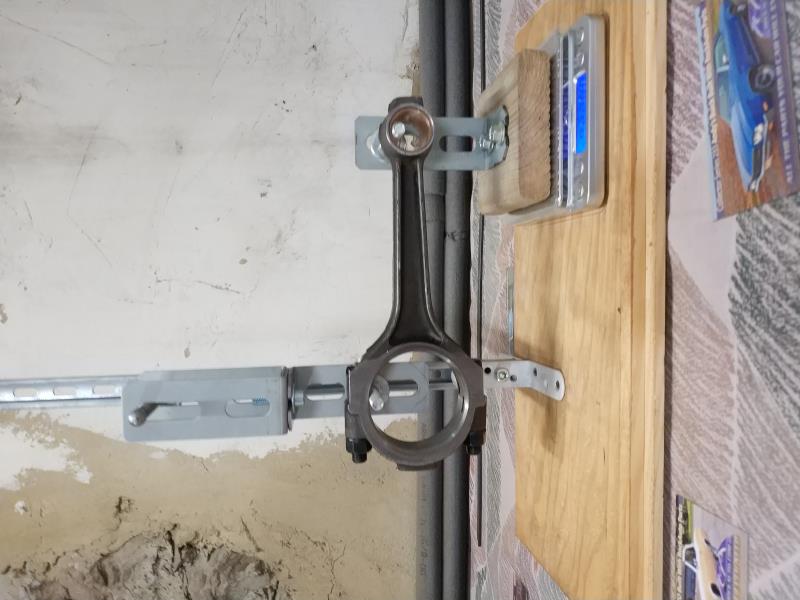
|
|
By Ted - 6 Years Ago
|
|
capelo (3/7/2020)
I have made modifications, but with the same result, the measurements are always different, I think I'm going to stop balancing the rods, is this operation necessary?
That's a 'Yes' on balancing the rods.
This may now be coming down to the resolution of the scale that you are using. You don't say how much variation you are getting in the readings. If the scale is reading in hundredths of a gram, then the hundredths resolution is going to be too fine depending upon the environment and fixtures being used. As long as the scale is consistent to a half a gram, you will be okay. Any air currents in the room will also play havoc with getting consistent readings. If you don’t have rollers as the contact points for the connecting rods on both ends, there will be enough friction or drag at those points to also prevent you from getting consistent readings. I have seen home-made rod measuring units that used paper clips as the contact points that worked satisfactorily.
|
|
By capelo - 6 Years Ago
|
I have done dry assembly of the rods with the pistons to measure the free space with the platform, then milling for a zero platform, these are the measurements, I would like your opinion on how much to mill.
N°1- 0,044"
N°2- 0,043"
N°3- 0,044"
N°4- 0,052"
N°5- 0,045"
N°6- 0,0425"
N°7- 0,040"
N°8- 0,046"
|
|
By capelo - 6 Years Ago
|
After the measurements and once disassembled everything I found these marks, is it normal or worrisome?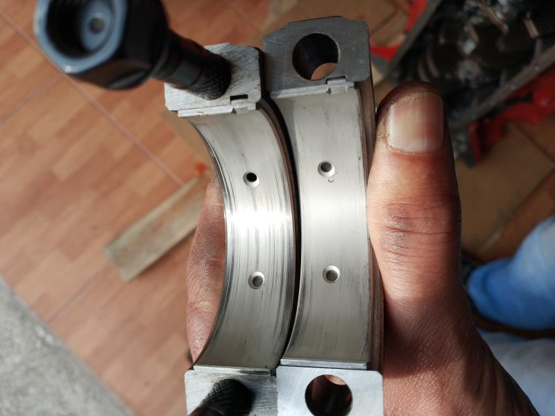 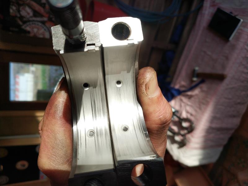  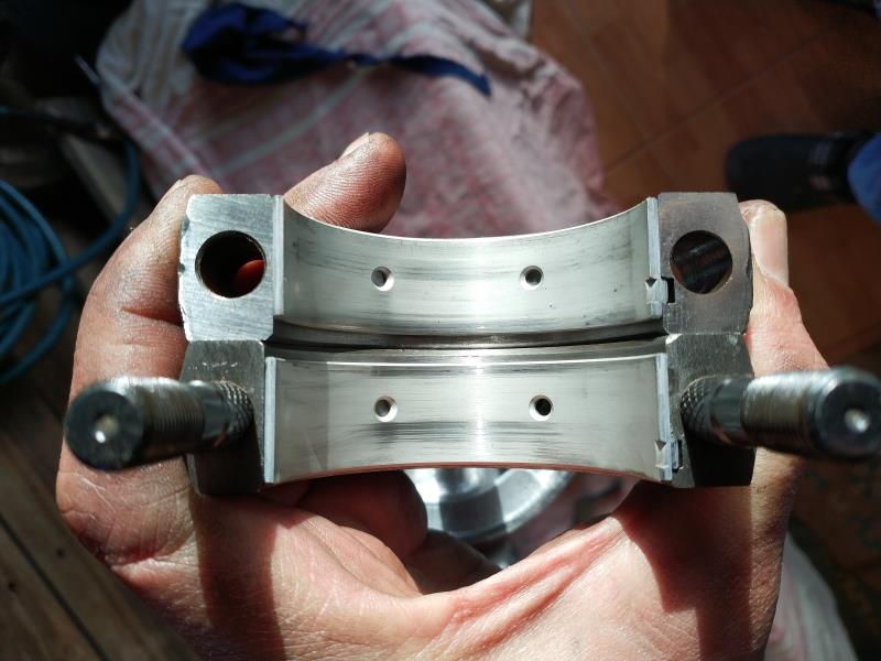 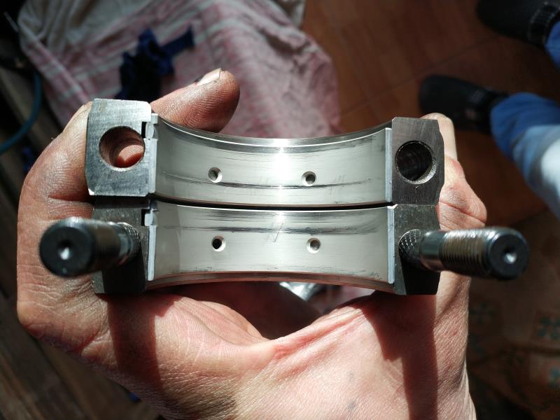 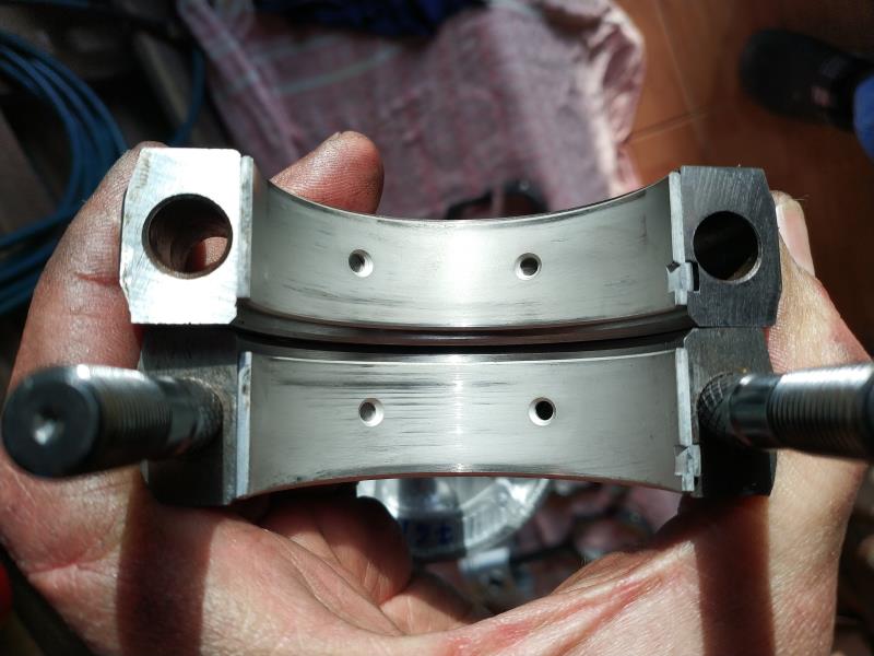 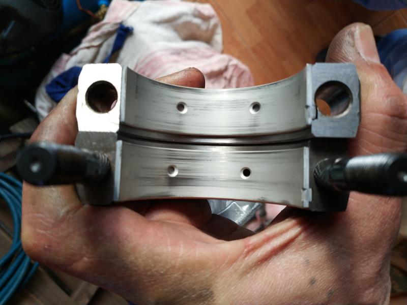
|
|
By capelo - 6 Years Ago
|
Ted (3/8/2020)
capelo (3/7/2020)
I have made modifications, but with the same result, the measurements are always different, I think I'm going to stop balancing the rods, is this operation necessary?That's a 'Yes' on balancing the rods.
This may now be coming down to the resolution of the scale that you are using. You don't say how much variation you are getting in the readings. If the scale is reading in hundredths of a gram, then the hundredths resolution is going to be too fine depending upon the environment and fixtures being used. As long as the scale is consistent to a half a gram, you will be okay. Any air currents in the room will also play havoc with getting consistent readings. If you don’t have rollers as the contact points for the connecting rods on both ends, there will be enough friction or drag at those points to also prevent you from getting consistent readings. I have seen home-made rod measuring units that used paper clips as the contact points that worked satisfactorily.
The accuracy of the scale is 0.1 gram. The variation in measurements can reach 5 grams. I think that the problem is the support on both sides, it must have too much friction and it does not get to focus since as it is set on a point it does not move from there and I do not know how to solve that, it comments on paper clip, but no I get to see that option, some image of some homemade gadget would be fine. The total weights if they are constant but separately never coincide is very frustrating.
Rod 1 - 678,2gr
2- 679,2gr
3- 682,4gr
4- 682,6gr
5- 683gr
6- 684,1gr
7- 682,7gr
8- 681,2gr
|
|
By Ted - 6 Years Ago
|
capelo (3/8/2020)
After the measurements and once disassembled everything I found these marks, is it normal or worrisome?
The wear marks on the bearings do look to be caused by dry assembling the parts without oil. That would be the result of metal to metal contact. Always use some form of oil or lubricant during any assembly of parts. Be sure all the parts are meticulously cleaned when the engine goes together. What you have right now will be okay if adequately lubed before reassembling.
|
|
By Ted - 6 Years Ago
|
capelo (3/8/2020)
The accuracy of the scale is 0.1 gram. The variation in measurements can reach 5 grams. I think that the problem is the support on both sides, it must have too much friction and it does not get to focus since as it is set on a point it does not move from there and I do not know how to solve that, it comments on paper clip, but no I get to see that option, some image of some homemade gadget would be fine. The total weights if they are constant but separately never coincide is very frustrating. Rod 1 - 678,2gr 2- 679,2gr 3- 682,4gr 4- 682,6gr 5- 683.0gr 6- 684,1gr 7- 682,7gr 8- 681,2gr
Until you get the repeatability of the weights consistent with your rod end weighing scale, there’s no need to try to weight balance the rod ends. Whatever you do, do not try to balance the rods based on the overall weights. That typically makes the end weights even more inconsistent. It’s not unusual for the rods themselves to have as much as a 5-6 gram variance at the ends when the scale readings are consistent so you’ll have to resolve that weight inconsistency problem before proceeding forward.
|
|
By capelo - 6 Years Ago
|
capelo (3/8/2020)
I have done dry assembly of the rods with the pistons to measure the free space with the platform, then milling for a zero platform, these are the measurements, I would like your opinion on how much to mill. N°1- 0,044" N°2- 0,043" N°3- 0,044" N°4- 0,052" N°5- 0,045" N°6- 0,0425" N°7- 0,040" N°8- 0,046"
Thanks for the comments, when reading dry assembly, act badly by not using some type of lubricant, now lubriciously more or will I have to polish the marks? about the measurements of the platforms any comments?
|
|
By Ted - 6 Years Ago
|
capelo (3/8/2020)
I have done dry assembly of the rods with the pistons to measure the free space with the platform (deck), then milling for a zero platform (deck), these are the measurements, I would like your opinion on how much to mill. N°1- 0,044" N°2- 0,043" N°3- 0,044" N°4- 0,052" N°5- 0,045" N°6- 0,0425" N°7- 0,040" N°8- 0,046"
With the #4 and #8 pistons being significantly deeper in their holes than the rest, I suspect you have connecting rod length and/or crankshaft stroke variance issues. Are all the connecting rods the same length? Is the stroke at all four rod journals the same? If not, then you can juggle the connecting rods within the various bores to get the piston to deck measurements closer to being equalized. Anytime the connecting rods and crankshafts are re-machined, the possibility that variances will be introduced where there were originally none is always increased. Once you get the measurements equalized to the point of being closer, then the decks can be machined to bring the pistons closer to the decks. If using composition head gaskets, then having the pistons level with the decks helps to maximize the compression ratio. A 'zero' deck is ideal in most instances wit h an iron headed Y.
|
|
By capelo - 6 Years Ago
|
Ted (3/10/2020)
capelo (3/8/2020)
I have done dry assembly of the rods with the pistons to measure the free space with the platform (deck), then milling for a zero platform (deck), these are the measurements, I would like your opinion on how much to mill. N°1- 0,044" N°2- 0,043" N°3- 0,044" N°4- 0,052" N°5- 0,045" N°6- 0,0425" N°7- 0,040" N°8- 0,046" With the #4 and #8 pistons being significantly deeper in their holes than the rest, I suspect you have connecting rod length and/or crankshaft stroke variance issues. Are all the connecting rods the same length? Is the stroke at all four rod journals the same? If not, then you can juggle the connecting rods within the various bores to get the piston to deck measurements closer to being equalized. Anytime the connecting rods and crankshafts are re-machined, the possibility that variances will be introduced where there were originally none is always increased. Once you get the measurements equalized to the point of being closer, then the decks can be machined to bring the pistons closer to the decks. If using composition head gaskets, then having the pistons level with the decks helps to maximize the compression ratio. A 'zero' deck is ideal in most instances wit h an iron headed Y.
I bought the crankshaft and everything is correct, the four connecting rod race is the same, the difference is in the length of the rods. But fixing this now is not possible and would be very expensive, which comments on juggling the rods, how would you advise its placement for a more balanced measure when machining the covers ?. the head gasket will be the one of BEST Gasket. thanks
|
|
By capelo - 6 Years Ago
|
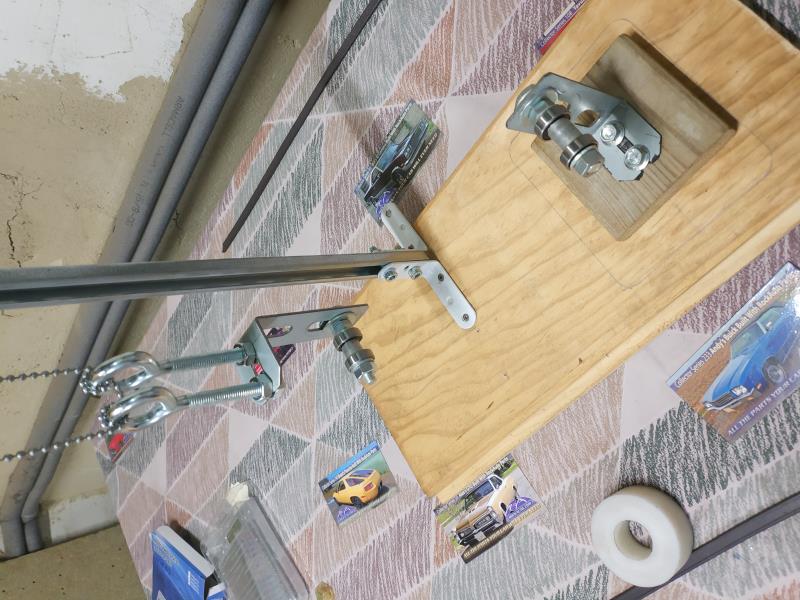
Ted (3/9/2020)
capelo (3/8/2020)
The accuracy of the scale is 0.1 gram. The variation in measurements can reach 5 grams. I think that the problem is the support on both sides, it must have too much friction and it does not get to focus since as it is set on a point it does not move from there and I do not know how to solve that, it comments on paper clip, but no I get to see that option, some image of some homemade gadget would be fine. The total weights if they are constant but separately never coincide is very frustrating. Rod 1 - 678,2gr 2- 679,2gr 3- 682,4gr 4- 682,6gr 5- 683.0gr 6- 684,1gr 7- 682,7gr 8- 681,2gr Until you get the repeatability of the weights consistent with your rod end weighing scale, there’s no need to try to weight balance the rod ends. Whatever you do, do not try to balance the rods based on the overall weights. That typically makes the end weights even more inconsistent. It’s not unusual for the rods themselves to have as much as a 5-6 gram variance at the ends when the scale readings are consistent so you’ll have to resolve that weight inconsistency problem before proceeding forward.
I have already been able to solve the problem for a constant measurement with an error of 0.5gr, the problem was the friction in the supports, I have placed some bearings for the solution, now I can continue with this work.
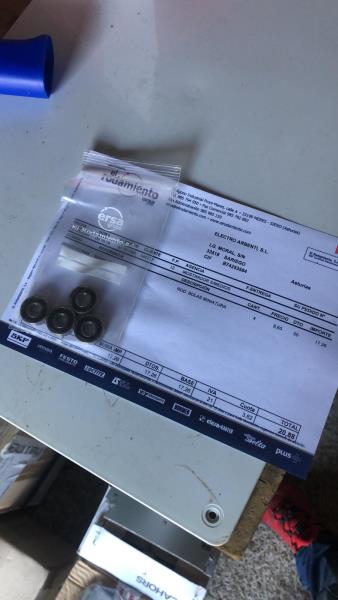
|
|
By Ted - 6 Years Ago
|
capelo (3/10/2020)
I bought the crankshaft and everything is correct, the four connecting rod race is the same, the difference is in the length of the rods. But fixing this now is not possible and would be very expensive, which comments on juggling the rods, how would you advise its placement for a more balanced measure when machining the covers ?. the head gasket will be the one of BEST Gasket. thanks
The block decks are typically high on their opposing ends and short on the other two. In redneck terms, the blocks are catty cornered or whopper-jawed. Now that you have some figures for your deck heights with all eight pistons, take measurements of those rod lengths and correlate them to the cylinders. What you essentially want are the short rods in the short cylinders and the long rods in the long cylinders. This is all assuming that both the crankshaft strokes and wrist pin locations (compression heights) are all the same to within one thousands of an inch.
In going through some of my notes on block decking for the Y’s, they are pretty much equal on which corners are high and which are low. Half of the blocks are high on cylinders 1 & 8 and low on cylinders 4 & 5 while the other half are a mix of the decks being either whopper-jawed on the opposite corners or the decks simply being higher on or at the same ends of the block.
|
|
By capelo - 6 Years Ago
|
|
Thanks for the help, I'm going to get to work on that, a question, can I somehow measure the block cover? I already did some. Check further and detect that in the threaded area for the fixing screws of the heads it is deformed outwards, between 0.001 and 0.002 ", and you can tell that sometimes I fixed the foot of the dial gauge on them, hence an erroneous measurement that I have already been able to check correctly on two cylinders with a variation of 0.004 ". I also checked with the highest and lowest connecting rods (4 and 7) in the same cylinder and it gives a difference between them of 0.004 ". I will continue working on this
|
|
By capelo - 6 Years Ago
|
I have made new measurements and I have tried to compensate the heights of the pistons, I do not know if what I did is correct since it gave me a lot of headache, if someone confirms the thought I would be very grateful, these are the measurements:
P1-.0.042
P2-0.043
P3-0.043
P4-0.046
P5-0.043
P6-0.042
P7-0.042
P8-0.046
I have tested pistons in cylinder 7 (4-5-6-7-8) and pistons in cylinder 4 (1-2-3-4-7) with these results:
C7: P7-0.042
P6-0.0405
P8-0.043
P5-0.041
P4-0.046
C4: P4-0.047
P7-0.042
P2-0.046
P1-0.048
P3-0.046
And my configuration that I do not know if it is correct:
(1-2-3-7)
(5-4-8-6)
|
|
By Ted - 6 Years Ago
|
|
capelo (3/12/2020)
I have made new measurements and I have tried to compensate the heights of the pistons, I do not know if what I did is correct since it gave me a lot of headache, if someone confirms the thought I would be very grateful, these are the measurements
That’s quite a bit of wrist pin variance. Were those pistons all checked with the same connecting rod?
capelo (3/12/2020)
Thanks for the help, I'm going to get to work on that, a question, can I somehow measure the block cover? I already did some.
If by ‘block cover’ you mean deck, then measuring the decks at all four corners accurately takes some specific tools not available to the mainstream hobbyist.
For a backyard way of doing this, just machine a steel bar or bushings the same diameter of the main holes without the bearings. If going the bushing route, then the internal hole size needs to fit a smaller diameter bar freely. The bar only needs to be long enough to fit into two journals at a time. With that bar in place between main journals, you can then use a depth micrometer to measure from the deck to the bar. Then add ½ the diameter of the bar to your measurement and you’ll have the deck height at the point you are measuring. I would measure from each side of the cylinder and record the measurements as such. Once you have all the measurements, you can then make a plan on how to square deck the block depending upon the wrist pins, rod lengths, and any variation that may occur in the crankshaft strokes.
|
|
By capelo - 6 Years Ago
|
Ted (3/13/2020)
capelo (3/12/2020)
I have made new measurements and I have tried to compensate the heights of the pistons, I do not know if what I did is correct since it gave me a lot of headache, if someone confirms the thought I would be very grateful, these are the measurementsThat’s quite a bit of wrist pin variance. Were those pistons all checked with the same connecting rod?capelo (3/12/2020)
Thanks for the help, I'm going to get to work on that, a question, can I somehow measure the block cover? I already did some.If by ‘block cover’ you mean deck, then measuring the decks at all four corners accurately takes some specific tools not available to the mainstream hobbyist.For a backyard way of doing this, just machine a steel bar or bushings the same diameter of the main holes without the bearings. If going the bushing route, then the internal hole size needs to fit a smaller diameter bar freely. The bar only needs to be long enough to fit into two journals at a time. With that bar in place between main journals, you can then use a depth micrometer to measure from the deck to the bar. Then add ½ the diameter of the bar to your measurement and you’ll have the deck height at the point you are measuring. I would measure from each side of the cylinder and record the measurements as such. Once you have all the measurements, you can then make a plan on how to square deck the block depending upon the wrist pins, rod lengths, and any variation that may occur in the crankshaft strokes.
Ted, you might have expected me wrong, what I did was test all the connecting rods on one side in the same cylinder with the same piston, plus one on the opposite side. So I did it in cylinder 7 and 4
|
|
By capelo - 6 Years Ago
|
well, I have already solved two problems, I have already been able to adjust all the pistons with a difference of 0.002 "and the platforms will be milled to find a zero (1,2,3,4-0,042") and (5,6,7, 8-0.043 "). On the connecting rods I have already been able to think them and balance all the weights with a margin of 0.5gr. Now I am going to send to balance the crankshaft, damper and flywheel, I have to calculate the weight Bob but I do not know exactly how is done, I have the following:
Piston plus pin -761 gr
Rings - 54,3vgr
Pin clik-2,4 gr
connecting rod small side- 180,4 gr
connecting rod large side-495 gr
|
|
By Ted - 6 Years Ago
|
|
Do you have the rod bearing weight?
|
|
By capelo - 6 Years Ago
|
Ted (3/15/2020)
Do you have the rod bearing weight?
45.6gr
|
|
By Ted - 6 Years Ago
|
The formula for calculating the balancing bobweight for a 90° V8 is typically 50% of the reciprocating weight and 100% of the rotating weight and then adding 2 grams of oil for each rod piston assembly. The oil number is controversial and I find that the 4 grams that is added for each bobweight (2 cylinders) is on the low side. For the Ford Y, I’ll use a minimum of 15 grams for the oil number for each bobweight. Total bobweight values are rounded up to the nearest whole gram value.
For your combination, the calculated bobweight value looks like this.
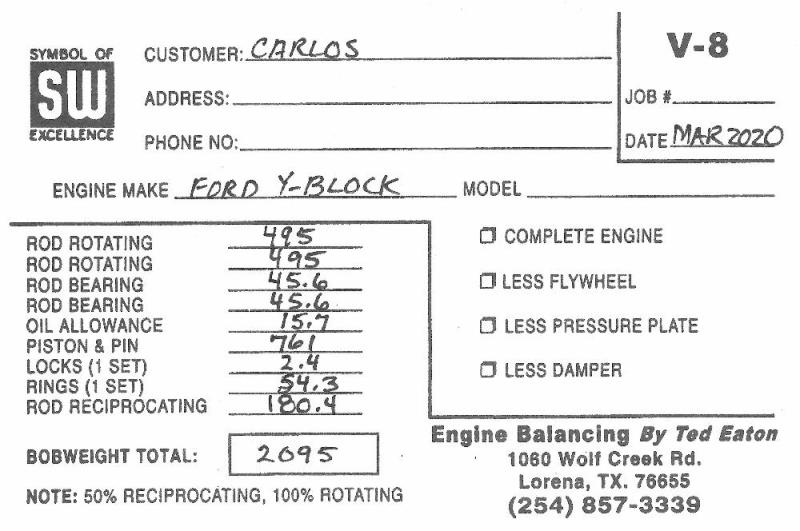
|
|
By capelo - 6 Years Ago
|
Ted (3/16/2020)
The formula for calculating the balancing bobweight for a 90° V8 is typically 50% of the reciprocating weight and 100% of the rotating weight and then adding 2 grams of oil for each rod piston assembly. The oil number is controversial and I find that the 4 grams that is added for each bobweight (2 cylinders) is on the low side. For the Ford Y, I’ll use a minimum of 15 grams for the oil number for each bobweight. Total bobweight values are rounded up to the nearest whole gram value. For your combination, the calculated bobweight value looks like this.
thank you very much Ted, you never fail, 🍻👍
|
|
By capelo - 6 Years Ago
|
|
I'm having trouble finding who performs the dynamic balancing of the crankshaft, they do it only static, around here it's not a common thing since there are usually no V-motors that go through the machine. I have found a company that does dynamic balancing but when talking to them they do not use the Bob counterweight to balance, I think it is because of what was said before they do not do it in V engines. To perform a dynamic balance of my crankshaft in that way would be worth to something, or would it be useless work and expense?
|
|
By Ted - 6 Years Ago
|
Dynamic balancing is required on crankshafts. As the weights of the pistons and rods are changed or altered from the original values, the crankshaft must be rebalanced accordingly. While something as thin as a flywheel can get away with being static balanced, anything with any length such as a crankshaft requires dynamic balancing to insure each end of the crankshaft is appropriately balanced. Here are a couple of pictures showing the fundamentals of static versus dynamic balancing.
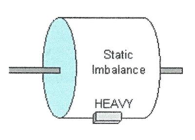 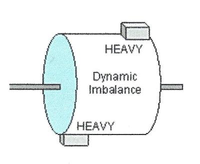
Here’s an article that was published in The Y-Block Magazine going into more detail.
http://www.eatonbalancing.com/2007/11/21/engine-balancing-part-1/
|
|
By capelo - 6 Years Ago
|
Ted (3/20/2020)
Dynamic balancing is required on crankshafts. As the weights of the pistons and rods are changed or altered from the original values, the crankshaft must be rebalanced accordingly. While something as thin as a flywheel can get away with being static balanced, anything with any length such as a crankshaft requires dynamic balancing to insure each end of the crankshaft is appropriately balanced. Here are a couple of pictures showing the fundamentals of static versus dynamic balancing.
Here’s an article that was published in The Y-Block Magazine going into more detail. http://www.eatonbalancing.com/2007/11/21/engine-balancing-part-1/
In my case I only have two options, or only static or dynamic balance but without placing the counterweights, which in that case I do not know if it is of any use. I had already read your articles and I know the importance of doing things well, thanks for sharing, but if a dynamic balance is not done, will this affect any type of circulation or only in high revs?
|
|
By Lord Gaga - 6 Years Ago
|
|
Capelo, Just curious. Where are you located?
|
|
By capelo - 6 Years Ago
|
Lord Gaga (3/20/2020)
Capelo, Just curious. Where are you located?
I am in Spain
|
|
By ian57tbird - 6 Years Ago
|
|
You must be in lockdown with the Yblock to keep you company at the moment. I believe things are bad over your way.
|
|
By capelo - 6 Years Ago
|
ian57tbird (3/20/2020)
You must be in lockdown with the Yblock to keep you company at the moment. I believe things are bad over your way.
Unfortunately this is the case in these difficult times, here there are already more than 20,000 infected and more than 1,000 deaths, we all have to fight together from our homes 💪💪
|
|
By Ted - 6 Years Ago
|
capelo (3/20/2020)
In my case I only have two options, or only static or dynamic balance but without placing the counterweights, which in that case I do not know if it is of any use. I had already read your articles and I know the importance of doing things well, thanks for sharing, but if a dynamic balance is not done, will this affect any type of circulation or only in high revs?
The crankshaft becomes underbalanced when not rebalanced to match the heavier combined weight of the rods, pistons, rings, bearings. Any crankshaft imbalance that is present in this circumstance becomes more severe at the rpm goes up. In this instance the crankshaft would need weight added to the counterweights at both ends in which to compensate. When going to the other end of the scale where the bobweight value is lighter than what the crankshaft was originally balanced to, then the crankshaft becomes overbalanced. In this instance the amount of imbalance at high rpm becomes less. To correct for those cases where the crankshaft is too heavy, weight is removed from the counterweights in which to compensate. In the grand scheme of things, crankshafts can tolerate a given amount of overbalance but are unforgiving in any amount of underbalance.
Part of the reasoning for balancing any engine during the rebuild process is to provide a balance that is better than what was supplied by the factory. A secondary reason is to compensate for any non-factory parts and machine work that is performed. While it’s a given that weight balancing only the connecting rods and pistons will help, only by rebalancing the crankshaft and other related parts is the job truly complete. If it’s not possible to balance the crankshaft, then at bare minimum at least have the flywheel, clutch, and pressure plate spin balanced on an arbor. Be sure the pressure plate is marked or indexed to the flywheel so it can be reinstalled on the flywheel at the same position it was balanced. The clutch disk is balanced separately on an arbor by itself and not with the flywheel and pressure plate assembly.
As the revised bobweight value for the crankshaft gets further away from the original factory balance value, so does the need for an increase in amount of work that is required to rebalance the crankshaft. In going through some of my notes on Ford Y-Block balancing, the typical bobweight values for stock 292 rebuilds are in the 2032-2116 gram range. Replacement piston weights are the cause for that range of values to be so wide spread. What I don’t have are the original piston weights with any of this data which would give a better feel for what the original factory bobweight value would have been. While the 2095 gram bobweight value that you need is within the aforementioned range, it is on the heavy side of average although it barely falls at the edge of the one standard deviation value from the mean of the values. Here’s the data from which I made those assumptions.

|
|
By capelo - 6 Years Ago
|
Ted (3/22/2020)
capelo (3/20/2020)
In my case I only have two options, or only static or dynamic balance but without placing the counterweights, which in that case I do not know if it is of any use. I had already read your articles and I know the importance of doing things well, thanks for sharing, but if a dynamic balance is not done, will this affect any type of circulation or only in high revs? The crankshaft becomes underbalanced when not rebalanced to match the heavier combined weight of the rods, pistons, rings, bearings. Any crankshaft imbalance that is present in this circumstance becomes more severe at the rpm goes up. In this instance the crankshaft would need weight added to the counterweights at both ends in which to compensate. When going to the other end of the scale where the bobweight value is lighter than what the crankshaft was originally balanced to, then the crankshaft becomes overbalanced. In this instance the amount of imbalance at high rpm becomes less. To correct for those cases where the crankshaft is too heavy, weight is removed from the counterweights in which to compensate. In the grand scheme of things, crankshafts can tolerate a given amount of overbalance but are unforgiving in any amount of underbalance. Part of the reasoning for balancing any engine during the rebuild process is to provide a balance that is better than what was supplied by the factory. A secondary reason is to compensate for any non-factory parts and machine work that is performed. While it’s a given that weight balancing only the connecting rods and pistons will help, only by rebalancing the crankshaft and other related parts is the job truly complete. If it’s not possible to balance the crankshaft, then at bare minimum at least have the flywheel, clutch, and pressure plate spin balanced on an arbor. Be sure the pressure plate is marked or indexed to the flywheel so it can be reinstalled on the flywheel at the same position it was balanced. The clutch disk is balanced separately on an arbor by itself and not with the flywheel and pressure plate assembly. As the revised bobweight value for the crankshaft gets further away from the original factory balance value, so does the need for an increase in amount of work that is required to rebalance the crankshaft. In going through some of my notes on Ford Y-Block balancing, the typical bobweight values for stock 292 rebuilds are in the 2032-2116 gram range. Replacement piston weights are the cause for that range of values to be so wide spread. What I don’t have are the original piston weights with any of this data which would give a better feel for what the original factory bobweight value would have been. While the 2095 gram bobweight value that you need is within the aforementioned range, it is on the heavy side of average although it barely falls at the edge of the one standard deviation value from the mean of the values. Here’s the data from which I made those assumptions.
Thank you very much Ted for this explanation and for the option presented. I'm going to try to do the best job possible in this section.
Changing the subject, if everything goes well at the end of the week I will have everything necessary to start the motor assembly and I would like to hear your advice and tricks for an optimal and smooth assembly.
Thank you
Carlos
|
|
By Ted - 6 Years Ago
|
capelo (3/23/2020)
...Changing the subject, if everything goes well at the end of the week I will have everything necessary to start the motor assembly and I would like to hear your advice and tricks for an optimal and smooth assembly. Thank you Carlos
The best piece of advice I can give you is to have someone familiar with engine building and/or assembly watching over your shoulder while you put the engine together. There are many little details that can get overlooked if you are not aware of them. There have been books written on this subject so there are only just a few items I can mention in just a few lines. But I will touch on some of the important things to watch for during the short block assembly.
Double clean everything before assembly
Use sealer on all oil galley plugs
Check the ring end gaps on the rings before installing them on the pistons
Bevel the edges of the oil ring rail gaps so there are no sharp edges to scratch the cylinder walls
Install the rings on the pistons using a tool for that purpose. Do not twist the rings onto the pistons.
Use plenty of oil or lubricant on all parts
Soak the timing chain in oil before installing
Insure that the camshaft turns freely
Verify that the camshaft end play is adequate
Make sure you have crankshaft end play when tightening the main caps
Use a feeler gauge between the rods when tightening those to insure you have no bearing twist
Make sure the connecting rods are free in their sideways movement on the journals after tightening the rod bolts.
Degree in the camshaft
If you are using a roller type of timing chain, be careful where you put pressure on the backside of the chain in which to remove it. Pry the chain forward by concentrating on the flats between the pins and not the pins themselves.
|
|
By capelo - 6 Years Ago
|
Ted (3/24/2020)
capelo (3/23/2020)
...Changing the subject, if everything goes well at the end of the week I will have everything necessary to start the motor assembly and I would like to hear your advice and tricks for an optimal and smooth assembly. Thank you Carlos The best piece of advice I can give you is to have someone familiar with engine building and/or assembly watching over your shoulder while you put the engine together. There are many little details that can get overlooked if you are not aware of them. There have been books written on this subject so there are only just a few items I can mention in just a few lines. But I will touch on some of the important things to watch for during the short block assembly. Double clean everything before assembly Use sealer on all oil galley plugs Check the ring end gaps on the rings before installing them on the pistons Bevel the edges of the oil ring rail gaps so there are no sharp edges to scratch the cylinder walls Install the rings on the pistons using a tool for that purpose. Do not twist the rings onto the pistons. Use plenty of oil or lubricant on all parts Soak the timing chain in oil before installing Insure that the camshaft turns freely Verify that the camshaft end play is adequate Make sure you have crankshaft end play when tightening the main caps Use a feeler gauge between the rods when tightening those to insure you have no bearing twist Make sure the connecting rods are free in their sideways movement on the journals after tightening the rod bolts. Degree in the camshaft If you are using a roller type of timing chain, be careful where you put pressure on the backside of the chain in which to remove it. Pry the chain forward by concentrating on the flats between the pins and not the pins themselves.
I will have the help of a mechanism but it is not experienced in this type of motors. I have acquired the book (Ford And Block Engines Hiw I rebuilt and Modify) and I have read many forums, posts and comments about these engines, but you never read or know everything, that's why I always like to ask. I am clear about the cleaning of the parts, sealing and pre-greasing of all the parts, checking the tolerances etc but there are always doubts that I will be moving. About what you said about the beveling of the edges of the oil rings, what you mean, I don't quite understand what it means, an image would open my eyes. I have some doubts about the ring mottling, about which is the first and second rings (I put pictures). I also have the question of whether or not some type of lubrication should be used both in the rings and in the cylinders when its installation. Since there is an expression in the ring information that I don't understand "NEVER USE PLATED RINGS IN PLATED CYLINDERS (CONTAC RING ENGINEERING FOR CORRECT APPLICATION)"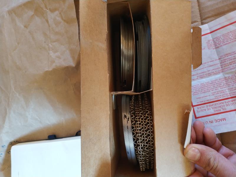 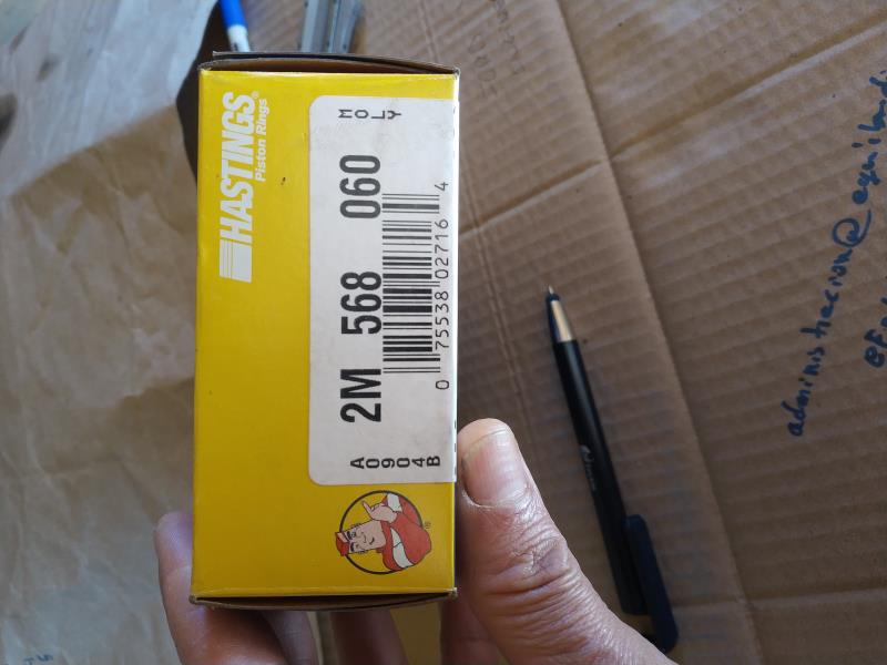
|
|
By kevink1955 - 6 Years Ago
|
I cannot help with the rings but if you are using the early edtion Eckman book do not use the photo of how to install the timing chain, it's wrong. I forget the number of pins between timing marks (12 I think) but the picture shows them on the wrong side of the engine. If your helper is not used to Y blocks he may want to line up the timing marks, dont to that either. Thats not how it works on a Y block
I think their was a good install guide on Ted's site, use it and you will have no problems
|
|
By capelo - 6 Years Ago
|
On the above mentioned I have read about the space between the ends of the rings has to be 0.004 "per inch of the cylinder hole, which in my case would be 3.8100" with what that space would be 0.015 ".
On the axial games and the clearances, I have read:
crankshaft end play 0.001 "to 0.006". Camshaft end play 0.001 "to 0.006". Maximum clearance between rods 0.019 ". Is all this correct or should we add something new?
|
|
By capelo - 6 Years Ago
|
Another question I have is about the position of the rods in the motor because the marks are not reliable and the previous assembly is not if it was adequate, the grooves where the bushings are fixed is the part that goes to the outside of the block ?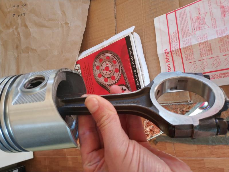
|
|
By capelo - 6 Years Ago
|
kevink1955 (3/24/2020)
I cannot help with the rings but if you are using the early edtion Eckman book do not use the photo of how to install the timing chain, it's wrong. I forget the number of pins between timing marks (12 I think) but the picture shows them on the wrong side of the engine. If your helper is not used to Y blocks he may want to line up the timing marks, dont to that either. Thats not how it works on a Y block I think their was a good install guide on Ted's site, use it and you will have no problems
thanks for the comment, I have that part well pointed, but since you comment, I will use Rollmaster red series and the camshaft that puts in the image below, the advance will be 2 ° as indicated by the paper, this is going for Ted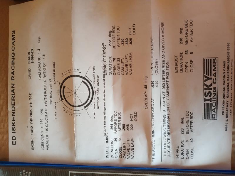
|
|
By Ted - 6 Years Ago
|
|
capelo (3/24/2020)
...About what you said about the beveling of the edges of the oil rings, what you mean, I don't quite understand what it means, an image would open my eyes. I have some doubts about the ring mottling, about which is the first and second rings (I put pictures). I also have the question of whether or not some type of lubrication should be used both in the rings and in the cylinders when its installation. Since there is an expression in the ring information that I don't understand "NEVER USE PLATED RINGS IN PLATED CYLINDERS (CONTAC RING ENGINEERING FOR CORRECT APPLICATION)
Your particular set of rings are okay for your cylinders. Use a light weight engine oil on the cylinder wall and the rings as you are installing the pistons to their bores.
Before you install the rings on the pistons, you will want to put them in the bores using an upside down piston to make the rings square with the bore. Check the ring end gaps with a feeler gauge. A rule of thumb is a minimum of 0.004” per inch of bore for the top rings and 0.003” per inch of bore for the second rings. On the oil rings, just make sure you have a minimum of 0.015” for the rails. Don’t’ be alarmed at a number much larger than this for the oil ring rails. Also do not make any modifications to the oil ring expanders.
If you need to adjust the gaps on the 1st and 2nd rings, do so with either a file or a piece of equipment designed for this. If just doing the gapping with a file, then support the ring ends between two pieces of wood in a vice and use the file cutting only inward to increase the existing gap. Once you are comfortable with the ring end gaps in each cylinder, then take a fine file or honing stone and dress the ring gap edges so that no sharp burrs are present. Those burrs can scratch the cylinder walls if they are present. On the oil rings, do the same thing on the gaps on those with a file or a dressing stone but always make your cuts going inward so that no potential burrs are in a position to ride on your freshly honed cylinder walls. Here’s a picture of the ring end gap with the ring edges being ‘dressed’.
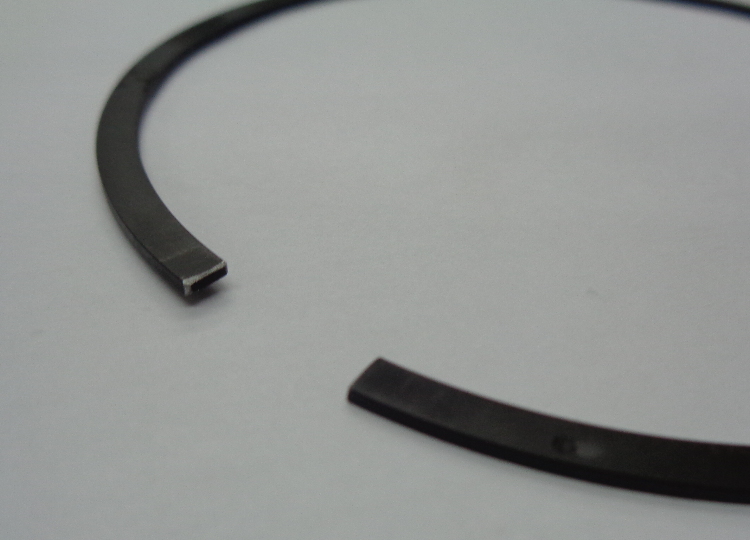
And here are some pictures of various ring gapping tools.
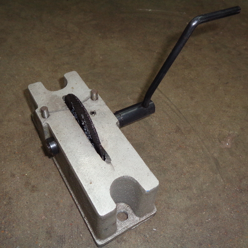

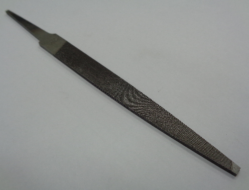
When installing the rings on the pistons, be sure to put them on the pistons orientated in regards to the tops and bottoms of the rings. If not marked accordingly, refer to the instruction sheet that comes with the ring package.
|
|
By Ted - 6 Years Ago
|
|
capelo (3/24/2020)
Another question I have is about the position of the rods in the motor because the marks are not reliable and the previous assembly is not if it was adequate, the grooves where the bushings are fixed is the part that goes to the outside of the block ?
For the Ford Y, the bearing tangs face the outside of the engine or away from the camshaft. If the rods are numbered correctly, those numbers will also face the outside of the engine or away from the camshaft. The double check for this is to look at the bearing in the rod. When the bearing is properly positioned on the journal, the bearing will be offset in the rod away from the journal’s side or edge. By design, the bearing is offset in the rod so that the bearing does not contact the journal radius at the edge of the journal.
|
|
By Ted - 6 Years Ago
|
capelo (3/24/2020)
kevink1955 (3/24/2020)
I cannot help with the rings but if you are using the early edtion Eckman book do not use the photo of how to install the timing chain, it's wrong. I forget the number of pins between timing marks (12 I think) but the picture shows them on the wrong side of the engine. If your helper is not used to Y blocks he may want to line up the timing marks, dont to that either. Thats not how it works on a Y block
I think that was a good install guide on Ted's thread, use it and you will have no problemsthanks for the comment, I have that part well pointed, but since you comment, I will use Rollmaster red series and the camshaft that puts in the image below, the advance will be 2 ° as indicated by the paper, this is going for Ted
While the camshaft has 2° of cam advance (4° at the crank) built into it, there’s no guarantee that is where the camshaft will install if just putting the crank gear at zero and going with 12 pins between the marks. Manufacturing variances in the various parts can have the camshaft installed far from desired which is why you must degree in the camshaft. When degreeing in the camshaft, target for 4-6° at the crankshaft. A bit more than 4° may be to your advantage as a new chain will stretch some initially thus retarding the camshaft some.
|
|
By Ted - 6 Years Ago
|
capelo (3/24/2020)
...On the axial games and the clearances, I have read: crankshaft end play 0.001 "to 0.006".+ Camshaft end play 0.001 "to 0.006". Maximum clearance between rods 0.019 ". Is all this correct or should we add something new?
As a general rule, it’s better to be on the loose side rather than the tight side when it comes to clearances.
I’m good with up to 0.010"-0.012” for crankshaft end play. I prefer 0.004”-0.006” for the camshaft end play. No less than 0.010” for connecting rod side clearance while I target for 0.025” rod side clearance on the performance applications. Keep in mind that having additional rod side clearance has no effect on oil pressure.
|
|
By capelo - 6 Years Ago
|
|
Thanks for the comments, I have checked all the rings and they are all within 0.015 ". I forgot a question, the camshaft is impregnated with a kind of grease, for assembly I have to clean it before?
|
|
By Ted - 6 Years Ago
|
capelo (3/25/2020)
...I forgot a question, the camshaft is impregnated with a kind of grease, for assembly I have to clean it before?
You will need to clean the camshaft before using it. The grease you see on the camshaft is a preservative or protective coating to keep the camshaft from rusting during storage. That coating is not a lubricant. As a result, the cam needs to be thoroughly cleaned when it comes out of the box and then the lobes coated with the moly lube supplied with the camshaft before installing it in the engine. Coat the bottoms of the lifters with that same moly lube but use only engine oil on the lifter shanks.
|
|
By capelo - 6 Years Ago
|
Ted (3/24/2020)
capelo (3/24/2020)
kevink1955 (3/24/2020)
I cannot help with the rings but if you are using the early edtion Eckman book do not use the photo of how to install the timing chain, it's wrong. I forget the number of pins between timing marks (12 I think) but the picture shows them on the wrong side of the engine. If your helper is not used to Y blocks he may want to line up the timing marks, dont to that either. Thats not how it works on a Y block
I think that was a good install guide on Ted's thread, use it and you will have no problemsthanks for the comment, I have that part well pointed, but since you comment, I will use Rollmaster red series and the camshaft that puts in the image below, the advance will be 2 ° as indicated by the paper, this is going for Ted While the camshaft has 2° of cam advance (4° at the crank) built into it, there’s no guarantee that is where the camshaft will install if just putting the crank gear at zero and going with 12 pins between the marks. Manufacturing variances in the various parts can have the camshaft installed far from desired which is why you must degree in the camshaft. When degreeing in the camshaft, target for 4-6° at the crankshaft. A bit more than 4° may be to your advantage as a new chain will stretch some initially thus retarding the camshaft some.
Thanks again, I will go to 6th then for my application.
On cleaning and lubricating the camshaft and lifters.
I suppose that the distribution system will happen the same, it is impregnated in grease for its conservation and I will have to wash it and then lubricate it.
|
|
By capelo - 6 Years Ago
|
I have any questions with the boards when to use, I put images: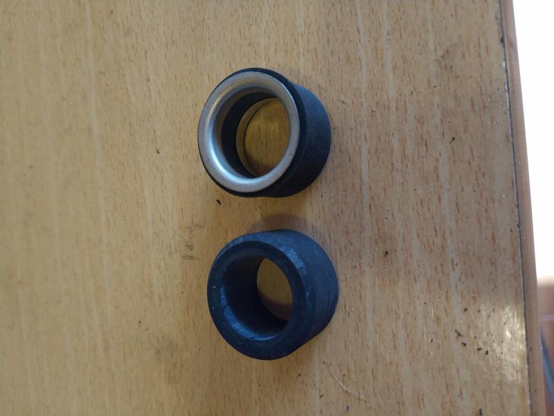 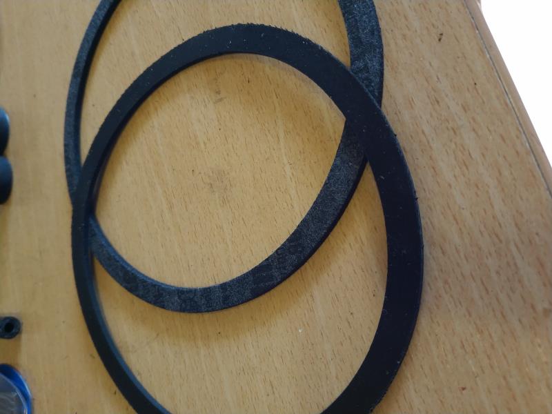
|
|
By capelo - 6 Years Ago
|
They could identify these Gasket:
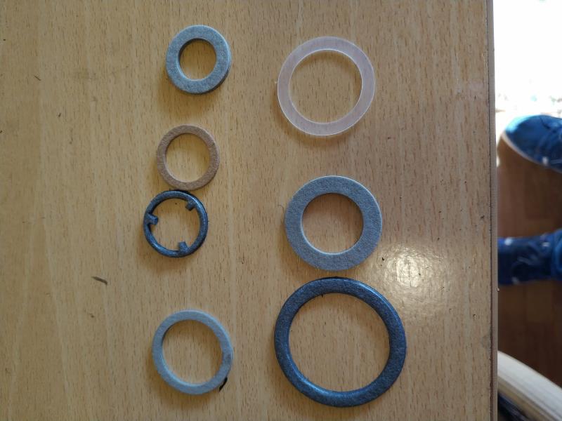
how clarification am I using this game: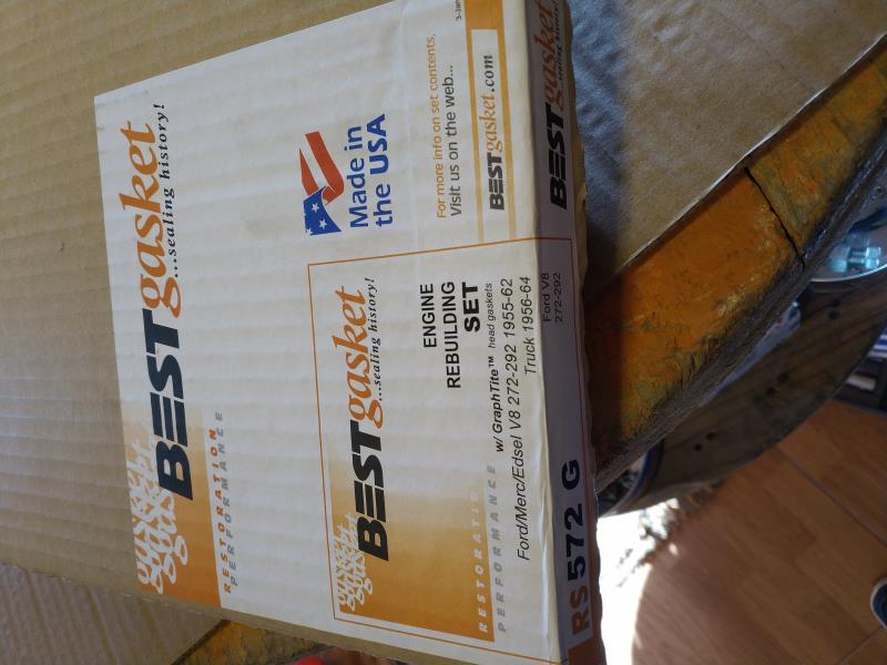
|
|
By paul2748 - 6 Years Ago
|
One of the blue ones s/b for the rear road draft tube for a TBird. I think it's the middle one on the right.
|
|
By Ted - 6 Years Ago
|
|
paul2748 (3/26/2020)
One of the blue ones s/b for the rear road draft tube for a TBird. I think it's the middle one on the right.
I’m thinking that the gasket for the valley cover mounted road draft tube is not shown as it’s considerably larger in diameter than those that are pictured. Here’s what I come up with for where some of those gaskets go.
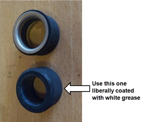
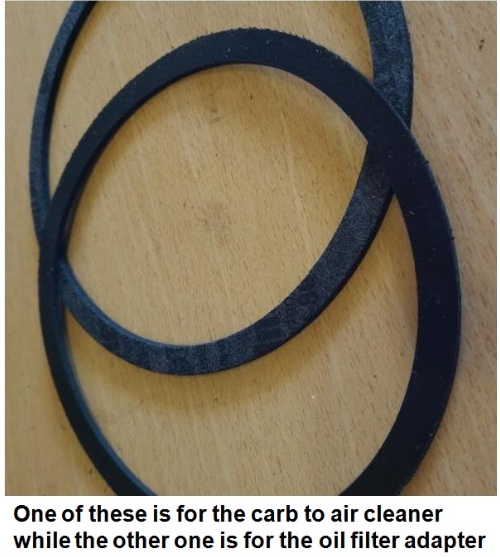
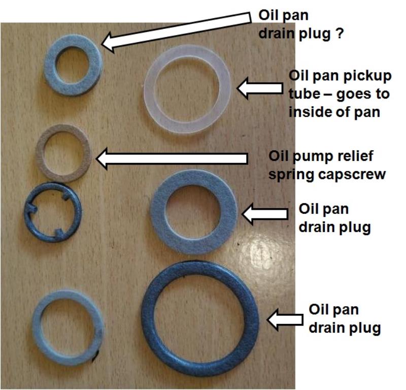
|
|
By capelo - 6 Years Ago
|
Thanks for all the comments, two of the seals indicated as the oil suction tube replace the copper ones?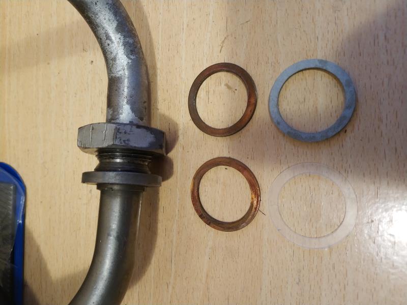
|
|
By capelo - 6 Years Ago
|
The gaskets indicated as for the air filter as well as the other for the oil filter adapter, in the image it is not seen but they are both of the same measurement one of them is rubber and the other is not the material, the question is which one to use. The one of the air filter is seen in the image with the largest diameter. Thank you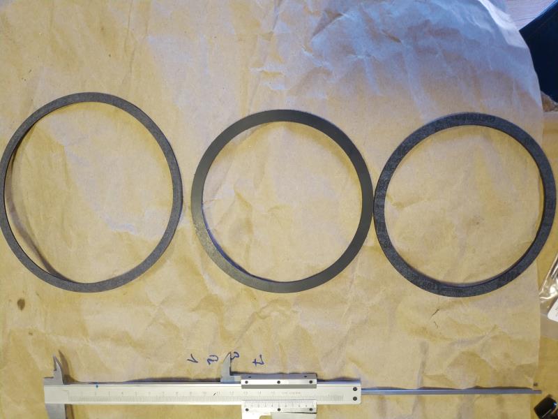 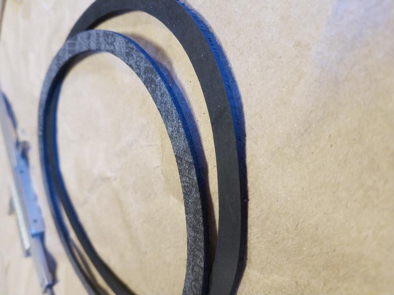
|
|
By capelo - 6 Years Ago
|
I have a problem with the camshaft screw, when inserting it I see that it immediately tightens and it shows forced I have bought with a similar one and it enters by hand, but in the old camshaft it did!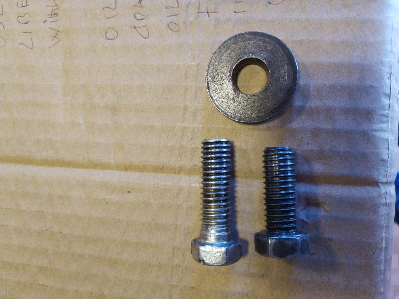
|
|
By Dave C - 6 Years Ago
|
Be careful you are not using a metric bolt.. All bolts are SAE in these engine..
I'm sure you already know this. Just a reminder in case it slipped your mind.
Dave
|
|
By capelo - 6 Years Ago
|
Dave C (3/27/2020)
Be careful you are not using a metric bolt.. All bolts are SAE in these engine.. I'm sure you already know this. Just a reminder in case it slipped your mind. Dave
Thanks for remembering, I always have it in mind 👍,
|
|
By capelo - 6 Years Ago
|
capelo (3/27/2020)
I have a problem with the camshaft screw, when inserting it I see that it immediately tightens and it shows forced I have bought with a similar one and it enters by hand, but in the old camshaft it did!
It may not express me, the screw on the left was in the old camshaft, but it does not fit the new one, the one on the left is one of the four that fix the gearbox to the bell, and that does In the new camshaft, I have to find one
|
|
By Hoosier Hurricane - 6 Years Ago
|
|
Notice that the threads on the bolt on the right are not as deep as the "standard" bolt on the left. That makes it sort of a self-locking bolt. Original bolts in a Y-Block camshaft are made that way. The right hand bolt appears to be the correct camshaft bolt for a Y-Block.
|
|
By Robs36Ford - 6 Years Ago
|
For the Oil filter adapter I would use the Fiber gasket as the Rubber one is for the Air cleaner to carb.
Best Gasket website has the list of parts:
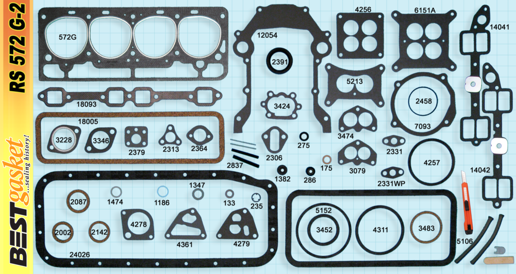
QTY PART NO CONTENTS
1 133 Oil Pan Drain Plug
1 175 Oil Pump Inlet Tube to Pan Seal
1 235 Oil Pump Relief Valve
1 275 Oil Pump Inlet Tube Seal
1 6286 Valve Stem Seal
1 1186 Oil Pan Drain Plug
1 1289 Down Draft Tube, T-Bird
1 1347 Oil Filter Mounting Bolt
6 1382 Push Rod/Valve Cover Grommet
1 1474 Oil Pump Inlet Tube Fitting
1 2002 Fuel Pump Bowl
1 2087 Fuel Pump Bowl, 54
X 1 2142 Fuel Pump Bowl, 55-57 T-Bird
1 2306 Fuel Pump Mounting
1 2313 Oil Pan to Inlet Tube
1 2331WP Water Pump Bypass
1 2331 Oil Pump Screen Cover
1 2364 Crankcase Ventilator
1 2379 Oil Pump Inlet Tube Flange
1 2391 Timing Cover Seal
1 2458 Oil Pump Cover-Rotor Type
1 2837 Rear Main Cap Seal Kit
3 3228 Exhaust Pipe Flange
3 3346 Exhaust Pipe Flange
1 3424 Oil Pump Cover-Gear Type
X 1 3452 Air Cleaner to Carburetor
1 3483 Crankcase Ventilator
X 1 4256 Carburetor Base
X 1 4257 Air Cleaner to Carburetor
1 4278 Water Outlet
1 4279 Oil Pump Mounting-Gear Type
1 4311 Oil Filter Mounting
X 1 4361 Oil Pump Mounting-Rotor Type
2 5106 Rear Main Seal-Rope
X 1 5152 Air Cleaner to Carburetor
X 2 6151A Carburetor Base
2 7093 Water Pump Mounting, 55-63
1 12054 Timing Cover
1 14041 Intake Manifold Right
1 14042 Intake Manifold Left
1 17022 Valley Cover
2 18005 Valve Cover
2 18093 Exhaust Manifold
1 24026 Oil Pan
1 Pinsee Armin
1 99999*** Special Knife Set - see Armin
ENGINE REBUILDING SET
RS572G-2
Ford V8 312 1956-57
x - indicates where part is not always found in other brands' sets
|
|
By capelo - 6 Years Ago
|
Hoosier Hurricane (3/27/2020)
Notice that the threads on the bolt on the right are not as deep as the "standard" bolt on the left. That makes it sort of a self-locking bolt. Original bolts in a Y-Block camshaft are made that way. The right hand bolt appears to be the correct camshaft bolt for a Y-Block.
Thanks for the clarification, I did not dare to insert the screw for fear of screaming the thread of the new camshaft 👍
|
|
By capelo - 6 Years Ago
|
Robs36Ford (3/28/2020)
For the Oil filter adapter I would use the Fiber gasket as the Rubber one is for the Air cleaner to carb. Best Gasket website has the list of parts: QTY PART NO CONTENTS 1 133 Oil Pan Drain Plug 1 175 Oil Pump Inlet Tube to Pan Seal 1 235 Oil Pump Relief Valve 1 275 Oil Pump Inlet Tube Seal 1 6286 Valve Stem Seal 1 1186 Oil Pan Drain Plug 1 1289 Down Draft Tube, T-Bird 1 1347 Oil Filter Mounting Bolt 6 1382 Push Rod/Valve Cover Grommet 1 1474 Oil Pump Inlet Tube Fitting 1 2002 Fuel Pump Bowl 1 2087 Fuel Pump Bowl, 54 X 1 2142 Fuel Pump Bowl, 55-57 T-Bird 1 2306 Fuel Pump Mounting 1 2313 Oil Pan to Inlet Tube 1 2331WP Water Pump Bypass 1 2331 Oil Pump Screen Cover 1 2364 Crankcase Ventilator 1 2379 Oil Pump Inlet Tube Flange 1 2391 Timing Cover Seal 1 2458 Oil Pump Cover-Rotor Type 1 2837 Rear Main Cap Seal Kit 3 3228 Exhaust Pipe Flange 3 3346 Exhaust Pipe Flange 1 3424 Oil Pump Cover-Gear Type X 1 3452 Air Cleaner to Carburetor 1 3483 Crankcase Ventilator X 1 4256 Carburetor Base X 1 4257 Air Cleaner to Carburetor 1 4278 Water Outlet 1 4279 Oil Pump Mounting-Gear Type 1 4311 Oil Filter Mounting X 1 4361 Oil Pump Mounting-Rotor Type 2 5106 Rear Main Seal-Rope X 1 5152 Air Cleaner to Carburetor X 2 6151A Carburetor Base 2 7093 Water Pump Mounting, 55-63 1 12054 Timing Cover 1 14041 Intake Manifold Right 1 14042 Intake Manifold Left 1 17022 Valley Cover 2 18005 Valve Cover 2 18093 Exhaust Manifold 1 24026 Oil Pan 1 Pinsee Armin 1 99999*** Special Knife Set - see Armin ENGINE REBUILDING SET RS572G-2 Ford V8 312 1956-57 x - indicates where part is not always found in other brands' sets
Thank you very much for this contribution, it is very helpful 👍
|
|
By capelo - 6 Years Ago
|
Where is Gasket going? when I took it apart there was no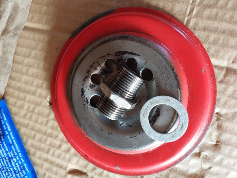
|
|
By Robs36Ford - 6 Years Ago
|
This is the front of the oil filter spin-on adapter, the gasket in your photo (Best Gasket no.1347) is not used with this adapter, the gasket (4311) goes at the back between the adapter and the engine block.
see item 6838 and 6749 here:

As you can see the bolt (tube) holds the adapter plate and gasket to the engine block. The bolt has no gasket needed. 6749 is included for the older canister cartridge filter housing.
From Ted's Website:
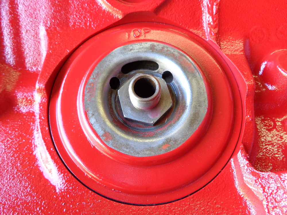
|
|
By capelo - 6 Years Ago
|
Robs36Ford (3/28/2020)
This is the front of the oil filter spin-on adapter, the gasket in your photo (Best Gasket no.1347) is not used with this adapter, the gasket (4311) goes at the back between the adapter and the engine block. see item 6838 and 6749 here: As you can see the bolt (tube) holds the adapter plate and gasket to the engine block. The bolt has no gasket needed. 6749 is included for the older canister cartridge filter housing. From Ted's Website:
Thank you very much for the clarification
|
|
By capelo - 6 Years Ago
|
|
Well I already have everything necessary to assemble the engine, I have a question before putting the pistons in the cylinders, can I clean them with WD40 oil or would it be better to do it with something else?
|
|
By capelo - 6 Years Ago
|
Another question, what's that extra hole for in the new oil pump?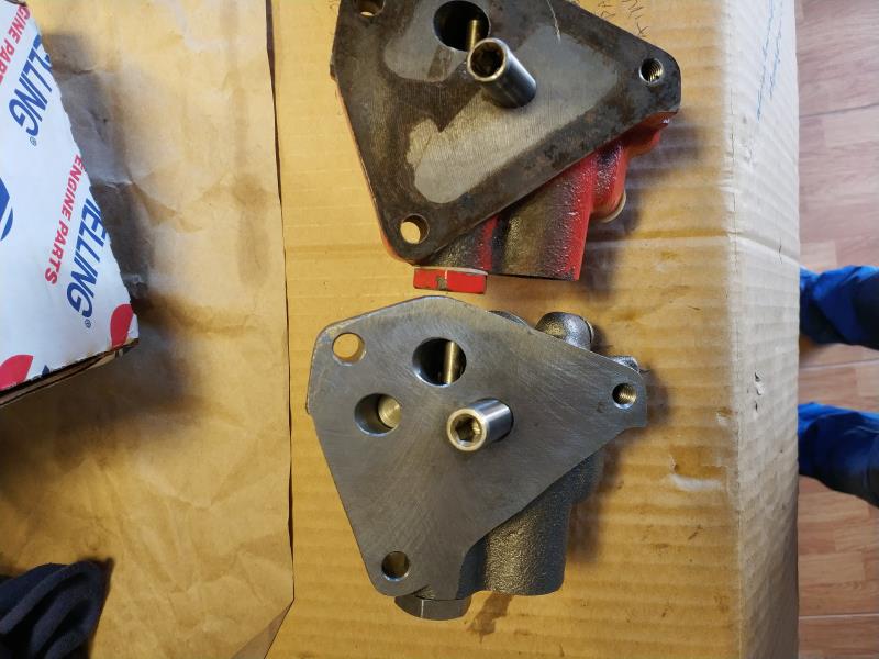
|
|
By DryLakesRacer - 6 Years Ago
|
|
WD40 is not a good oil. It’s a water displacement fluid. You can still wipe everything with it but I would wipe your cylinder walls with auto trans fluid Or Marvel mystery oil on a white paper towel Over and over until the paper towel stays red. Cam should have the recommended cam assembly lube and the rods/mains assembly lube. I use Lucas since I can find it. I use it on all metal to metal surfaces, push rod ends, Rocker tips, cam gears/chains. Etc... everyone seems to have their own opinions on this. Good luck
|
|
By capelo - 6 Years Ago
|
DryLakesRacer (3/31/2020)
WD40 is not a good oil. It’s a water displacement fluid. You can still wipe everything with it but I would wipe your cylinder walls with auto trans fluid Or Marvel mystery oil on a white paper towel Over and over until the paper towel stays red. Cam should have the recommended cam assembly lube and the rods/mains assembly lube. I use Lucas since I can find it. I use it on all metal to metal surfaces, push rod ends, Rocker tips, cam gears/chains. Etc... everyone seems to have their own opinions on this. Good luck
Thanks for the recommendations, I take note of it
|
|
By Ted - 6 Years Ago
|
|
capelo (3/31/2020)
Another question, what's that extra hole for in the new oil pump?
Different manufacturers do things differently for similar parts. Your new oil pump has the hole for one of the spur gear shafts drilled completely through the block side of the housing while the older pump you have does not have that same hole drilled all the way through.
While we are on the subject of oil pumps, it’s prudent to disassemble any new oil pump and examine its inner workings thoroughly for any problems. Be sure the oil pressure relief valve works freely. If there are any machining chips to be found, the oil pressure relief valve cavity is a place where they can be hiding. A good cleaning and some fresh lube on the gears and the pump is ready to be reassembled.
|
|
By capelo - 6 Years Ago
|
Ted (3/31/2020)
capelo (3/31/2020)
Another question, what's that extra hole for in the new oil pump?Different manufacturers do things differently for similar parts. Your new oil pump has the hole for one of the spur gear shafts drilled completely through the block side of the housing while the older pump you have does not have that same hole drilled all the way through. While we are on the subject of oil pumps, it’s prudent to disassemble any new oil pump and examine its inner workings thoroughly for any problems. Be sure the oil pressure relief valve works freely. If there are any machining chips to be found, the oil pressure relief valve cavity is a place where they can be hiding. A good cleaning and some fresh lube on the gears and the pump is ready to be reassembled.
When disassembling the gasket are not destroyed? or can they be recovered ?, disassemble the old pump to see its condition, check it and reassemble it since it had no wear or marks, but I had to use new gasket for it and now I don't have a new set
|
|
By capelo - 6 Years Ago
|
I have another question, I have read Ted's article on mounting the neoprene rear seal several times, I don't understand where this applies:
KW Copper Coat or similar type of sealer is applied to the retainer flats where it mates to the block. At this point, the remaining rear seal half is laid into the retainer groove with emphasis being put on insuring that the lip of the seal faces the inside of the engine when the retainer is bolted in place.
|
|
By Lord Gaga - 6 Years Ago
|
|
Do NOT use paper towels to wipe any internal parts of your engine!!! Use lint free cloths only please!!
|
|
By DryLakesRacer - 6 Years Ago
|
|
Oops that was me, thinking of the past. I’ve collected white lint free what look to be paper but are not from Kimberly-Clark. Those are what I use. Sorry...
|
|
By Ted - 6 Years Ago
|
capelo (4/1/2020)
I have another question, I have read Ted's article on mounting the neoprene rear seal several times, I don't understand where this applies: KW Copper Coat or similar type of sealer is applied to the retainer flats where it mates to the block. At this point, the remaining rear seal half is laid into the retainer groove with emphasis being put on insuring that the lip of the seal faces the inside of the engine when the retainer is bolted in place.
Here are a couple of pictures pointing to where sealer is applied to insure that there is no oil seepage occurring at the parting line of the block and rear seal retainer. I use K&W Copper Coat on those areas but any suitable sealer should prove to be adequate there. The point is to not install the rear seal retainer dry or without sealer there.
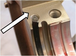 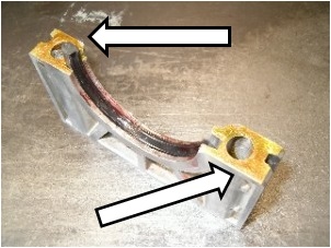
|
|
By Ted - 6 Years Ago
|
capelo (4/1/2020)
When disassembling the gasket are not destroyed? or can they be recovered ?, disassemble the old pump to see its condition, check it and reassemble it since it had no wear or marks, but I had to use new gasket for it and now I don't have a new set
That’s a ‘Yes’ in that the original gaskets on the spur gear pumps are typically destroyed when removing the oil pump cover for the first time. By the same token, I’ll not use any oil pump within an engine without first disassembling it and giving it a thorough inspection. Best Gasket does supply new gasket for the spur gear oil pumps in the rebuild gasket set but if you’ve already used that gasket on the old oil pump, you may be able to salvage that particular gasket and reuse it. I have extras but it would require mailing to Spain which could take awhile. If I need to mail you some gaskets, just send me your mailing address.
|
|
By capelo - 6 Years Ago
|
Ted (4/1/2020)
capelo (4/1/2020)
I have another question, I have read Ted's article on mounting the neoprene rear seal several times, I don't understand where this applies: KW Copper Coat or similar type of sealer is applied to the retainer flats where it mates to the block. At this point, the remaining rear seal half is laid into the retainer groove with emphasis being put on insuring that the lip of the seal faces the inside of the engine when the retainer is bolted in place. Here are a couple of pictures pointing to where sealer is applied to insure that there is no oil seepage occurring at the parting line of the block and rear seal retainer. I use K&W Copper Coat on those areas but any suitable sealer should prove to be adequate there. The point is to not install the rear seal retainer dry or without sealer there.
Thank you very much Ted, now I have everything clearer
|
|
By capelo - 6 Years Ago
|
Ted (4/1/2020)
capelo (4/1/2020)
When disassembling the gasket are not destroyed? or can they be recovered ?, disassemble the old pump to see its condition, check it and reassemble it since it had no wear or marks, but I had to use new gasket for it and now I don't have a new set That’s a ‘Yes’ in that the original gaskets on the spur gear pumps are typically destroyed when removing the oil pump cover for the first time. By the same token, I’ll not use any oil pump within an engine without first disassembling it and giving it a thorough inspection. Best Gasket does supply new gasket for the spur gear oil pumps in the rebuild gasket set but if you’ve already used that gasket on the old oil pump, you may be able to salvage that particular gasket and reuse it. I have extras but it would require mailing to Spain which could take awhile. If I need to mail you some gaskets, just send me your mailing address.
Thank you very much again, I highly consider your offer, I think I have another gasket. It is I who will have to send you something for your help for so long. He is a great person 👍
|
|
By capelo - 6 Years Ago
|
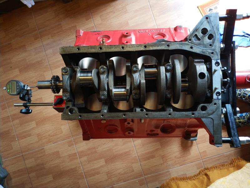 I have already installed the crankshaft and of course the rear neoprene seal, on this I have two comments, first: the final axial play is 0.004 ", I do not know if this is sufficient or if it can be improved. Second: when introducing the black seals sides, these entered with the hand without effort and when introducing the nails to the end the seals are about 5mm lower than the cover, this is not if it is normal, fill the final hole with RTV black sealant I have already installed the crankshaft and of course the rear neoprene seal, on this I have two comments, first: the final axial play is 0.004 ", I do not know if this is sufficient or if it can be improved. Second: when introducing the black seals sides, these entered with the hand without effort and when introducing the nails to the end the seals are about 5mm lower than the cover, this is not if it is normal, fill the final hole with RTV black sealant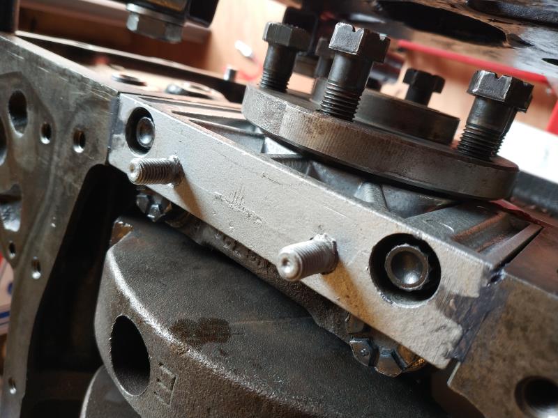
|
|
By capelo - 6 Years Ago
|
I have disassembled the new oil pump and the gasket has come out of a piece, I still have a new one, I am going to wash and oil and reassemble, does the gasket have some kind of sealant?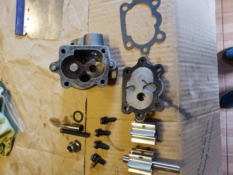
|
|
By capelo - 6 Years Ago
|
Lord Gaga (4/1/2020)
Do NOT use paper towels to wipe any internal parts of your engine!!! Use lint free cloths only please!!
👍
|
|
By MplsMike - 6 Years Ago
|
I don’t know about the rest of you, but it has been a lot of fun following this thread. Capelo, you have been very thorough and careful; all of the experts on the forum have been very helpful, with a big shout out to Ted for his detailed explanations. This has been a great learning experience for a novice like me.
I can’t wait for the rest of the story to unfold. Capelo, I hope you can post a video of your running engine soon! Stay safe!
Thanks, everyone
|
|
By capelo - 6 Years Ago
|
MplsMike (4/3/2020)
I don’t know about the rest of you, but it has been a lot of fun following this thread. Capelo, you have been very thorough and careful; all of the experts on the forum have been very helpful, with a big shout out to Ted for his detailed explanations. This has been a great learning experience for a novice like me. I can’t wait for the rest of the story to unfold. Capelo, I hope you can post a video of your running engine soon! Stay safe! Thanks, everyone
Thank you very much, I'm glad this works for more people, there are very wise people here. I will continue putting the advances and of course all my doubts. Take care and strength
|
|
By Dave C - 6 Years Ago
|
capelo (4/2/2020)
I have disassembled the new oil pump and the gasket has come out of a piece, I still have a new one, I am going to wash and oil and reassemble, does the gasket have some kind of sealant?
Depending on how long it would be before installing and the first start, I would recommend using some sort of assembly lube on the internal surfaces of the oil pump as regular oil could "drain" off and cause issues with the pump losing it prime and not want to pick up the oil on initial start. This is no real issue if you prime the oil system prior to starting the engine.
Just some thoughts as I have had issues a couple of times with engines/new oil pumps refusing to pick up oil even using a priming tool..
Dave
|
|
By capelo - 6 Years Ago
|
I have already been able to solve the low crankshaft end play, the problem was in the bearing of the third bed, I think it may now be within the scope of what has been said.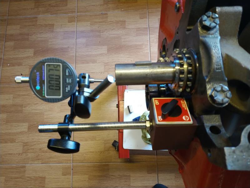 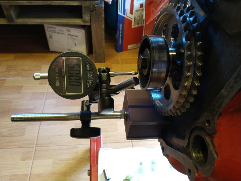
|
|
By capelo - 6 Years Ago
|
Dave C (4/3/2020)
capelo (4/2/2020)
I have disassembled the new oil pump and the gasket has come out of a piece, I still have a new one, I am going to wash and oil and reassemble, does the gasket have some kind of sealant? Depending on how long it would be before installing and the first start, I would recommend using some sort of assembly lube on the internal surfaces of the oil pump as regular oil could "drain" off and cause issues with the pump losing it prime and not want to pick up the oil on initial start. This is no real issue if you prime the oil system prior to starting the engine. Just some thoughts as I have had issues a couple of times with engines/new oil pumps refusing to pick up oil even using a priming tool.. Dave
Thanks for the comment, my intention is to rotate the pump before starting until I see pressure on the oil gauge and see that the oil reaches the rocker arms. On the gasket of the pump, does it have a sealant or, like the gasket that connects it to the block, does it carry nothing?
|
|
By capelo - 6 Years Ago
|
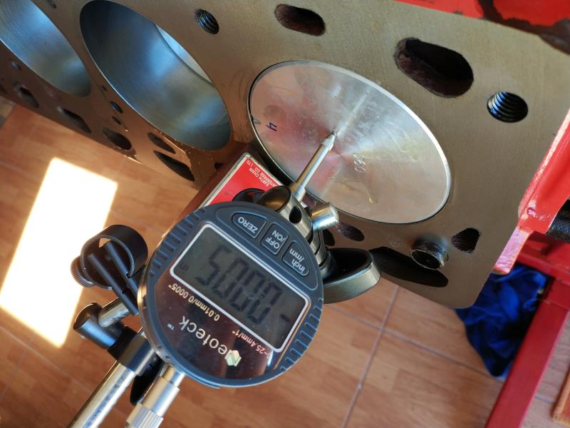
the pistons are in place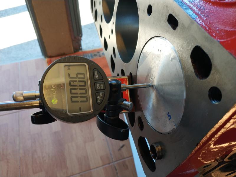 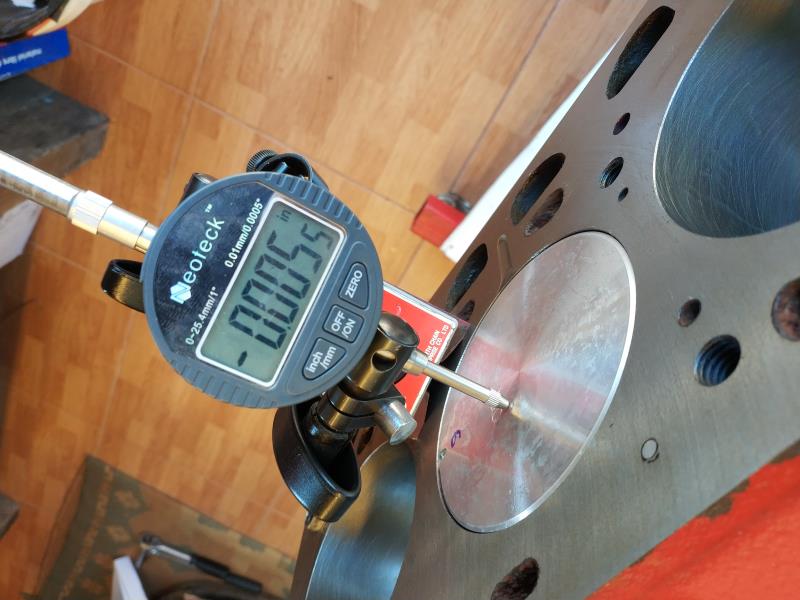 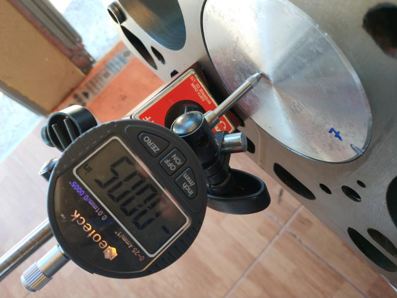 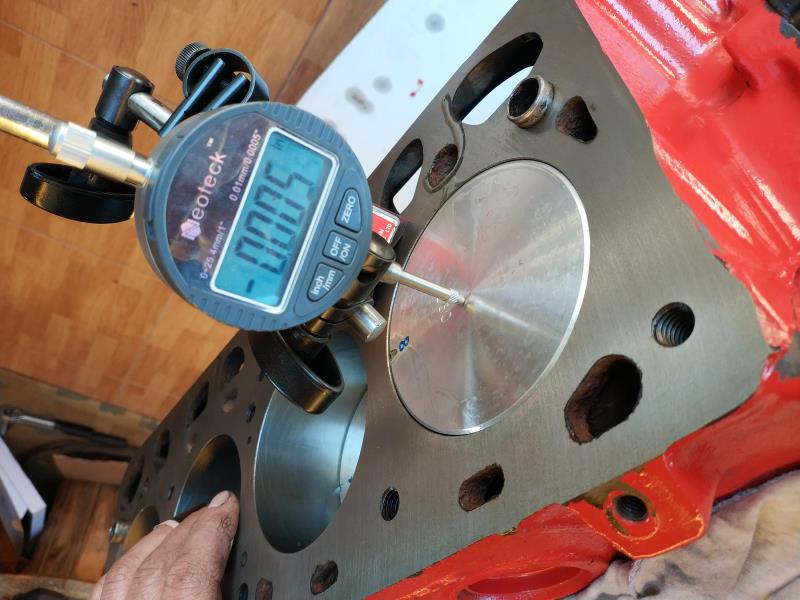 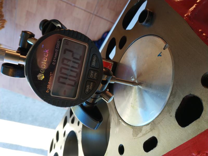 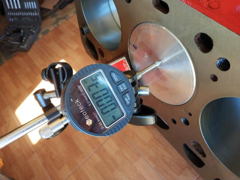 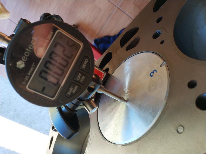
|
|
By Ted - 6 Years Ago
|
|
I don’t use any sealer on either the oil pump cover face plate or the oil pump to block interface. That’s a personal preference on my end. If you do use a sealer, just be sure it is of a semi-fluid viscosity (K&W Copper Coat) and not a sealer that’s too thick to allow the parts to seat fully or uniformly or squeezes the excess into places it does not belong.
|
|
By capelo - 6 Years Ago
|
Ted (4/4/2020)
I don’t use any sealer on either the oil pump cover face plate or the oil pump to block interface. That’s a personal preference on my end. If you do use a sealer, just be sure it is of a semi-fluid viscosity (K&W Copper Coat) and not a sealer that’s too thick to allow the parts to seat fully or uniformly or squeezes the excess into places it does not belong.
Thanks Ted, I get on with her, 👍 take care
|
|
By capelo - 6 Years Ago
|
|
The gasket of the oil filter adapter, is a sealant not used either?
|
|
By capelo - 6 Years Ago
|
I think I have verified this, but one more opinion helps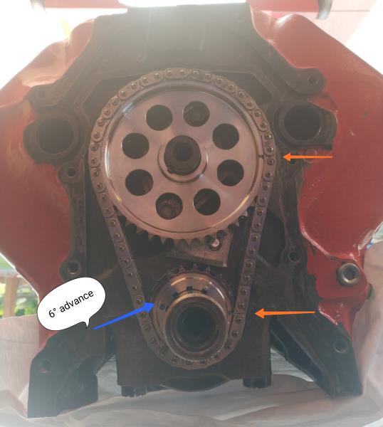
|
|
By capelo - 6 Years Ago
|
wanted I saw this on Ted's page, I think I got the camshaft setting wrong. I have the twelve pins between the only two marks they bring, do I have to count the twelve from the tooth marked in the drawing as A6?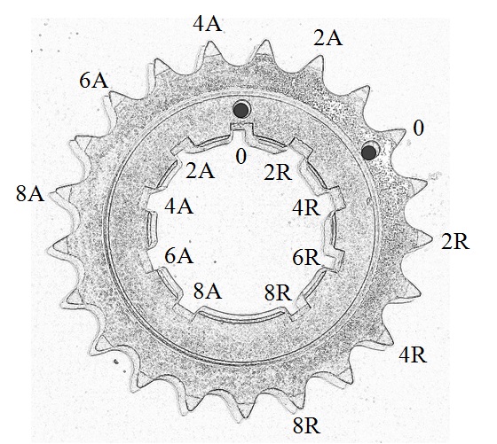
|
|
By 2721955meteor - 6 Years Ago
|
my opinion oaths post is it has got far to long,also it promotes exotic over kill on rebuilding a Y block.the real world if iwe want to compet in a hp race it would not make cents to start with a 292 or a 312. Ted has proven he can make a old dog make huge hp numbers, i have great respect for his achievements. the 292 post showes how to piss away big bucks to accomplish nor much.
i would venture to say starting with a sound core a 292 /or 312 could be built for under 4000 canadian that would be very dependable and fun to drive., that would detail come cents in reusability, new parts are reasonable and my idea is ys ran 100000 miles with cast pistons and rings,reground cams and lifters, stock timing chain etce
i ame sure my post will ster up some rebuttal,i look forward to that
|
|
By Dave C - 6 Years Ago
|
capelo (4/3/2020)
Dave C (4/3/2020)
capelo (4/2/2020)
I have disassembled the new oil pump and the gasket has come out of a piece, I still have a new one, I am going to wash and oil and reassemble, does the gasket have some kind of sealant? Depending on how long it would be before installing and the first start, I would recommend using some sort of assembly lube on the internal surfaces of the oil pump as regular oil could "drain" off and cause issues with the pump losing it prime and not want to pick up the oil on initial start. This is no real issue if you prime the oil system prior to starting the engine. Just some thoughts as I have had issues a couple of times with engines/new oil pumps refusing to pick up oil even using a priming tool.. Dave Thanks for the comment, my intention is to rotate the pump before starting until I see pressure on the oil gauge and see that the oil reaches the rocker arms. On the gasket of the pump, does it have a sealant or, like the gasket that connects it to the block, does it carry nothing?
You should not need any sealant on that gasket. Both sides are a machined surface.
Dave
|
|
By ian57tbird - 6 Years Ago
|
|
Just referring to your post where you are measuring deck clearance with a dial gauge. I have not found that it easy to get a consistent reading when releasing and reattaching a magnetic base. For that I would trust a good straight edge and feeler gauges more. Others might have a different opinion.
|
|
By Ted - 6 Years Ago
|
capelo (4/4/2020)
Not sure where you are going with the picture of the front of your engine. I’m assuming you degreed in the camshaft and need to advance it 6° to put it where you need it? If you have not started the degree in process yet, then you will need to start the process with the lower gear in the zero position. Assume nothing at this point. Because of manufacturing variances, the camshaft will likely have to be advanced or retarded to some degree to get it exactly where you require it. Because I have come across different camshafts being as much as 18° advanced or retarded when the timing sets were simply installed with the marks properly aligned, it’s imperative that the camshaft be degreed in during its installation. Taking it to the next level will have you checking the cam timing on at least one cylinder on each bank to insure that the camshaft was ground on the correct lifter bank angle.
Unfortunately most engines will crank and run regardless if they are off as much as a full tooth on the timing set but the key here is you want it to run optimally; hence the reasoning for at least checking the camshaft timing.
The Rollmaster crank gear is only marked on the outer row with the zero position for the twelve pins. If moving the gear to either a advanced or retarded keyway position, you’ll need to put some kind of mark at the outer row of teeth so you can get a true twelve tooth count to the new mark.
Here’s the picture with new marks added for the 6° advance position to help clarify how to count the twelve pins when moving the crank gear position.
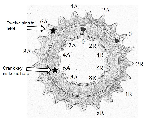
|
|
By Ted - 6 Years Ago
|
Here’s another option for the link count on the timing chain when moving the crank gear to any position other than zero. In this particular instance, you will be using the outside zero mark and then using a revised link count when the lower gear is in any position other than the keyway zero position. Here’s a picture of the various link counts as related to the keyway slots.
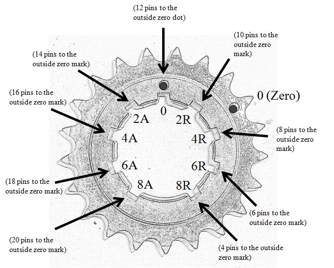
|
|
By capelo - 6 Years Ago
|
Ted (4/4/2020)
capelo (4/4/2020)
Not sure where you are going with the picture of the front of your engine. I’m assuming you degreed in the camshaft and need to advance it 6° to put it where you need it? If you have not started the degree in process yet, then you will need to start the process with the lower gear in the zero position. Assume nothing at this point. Because of manufacturing variances, the camshaft will likely have to be advanced or retarded to some degree to get it exactly where you require it. Because I have come across different camshafts being as much as 18° advanced or retarded when the timing sets were simply installed with the marks properly aligned, it’s imperative that the camshaft be degreed in during its installation. Taking it to the next level will have you checking the cam timing on at least one cylinder on each bank to insure that the camshaft was ground on the correct lifter bank angle. Unfortunately most engines will crank and run regardless if they are off as much as a full tooth on the timing set but the key here is you want it to run optimally; hence the reasoning for at least checking the camshaft timing. The Rollmaster crank gear is only marked on the outer row with the zero position for the twelve pins. If moving the gear to either a advanced or retarded keyway position, you’ll need to put some kind of mark at the outer row of teeth so you can get a true twelve tooth count to the new mark. Here’s the picture with new marks added for the 6° advance position to help clarify how to count the twelve pins when moving the crank gear position.
Following his camshaft graduation tutorial and using the central lobe mode, he throws me this data:
53 ° ATDC. ATDC 147 ° that together give us 200 ° and divided into two fa 100 °, which treated at 110 ° announced in the cam are 10 °.
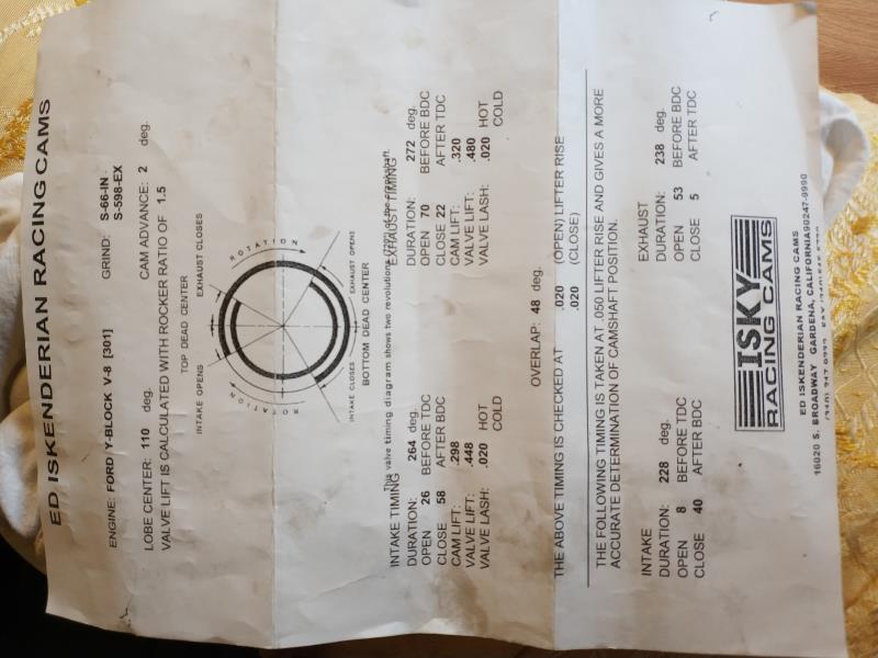
Now, how should I finally graduate distribution?
|
|
By capelo - 6 Years Ago
|
And here is the total advance before deadlock greater than 0.050 "
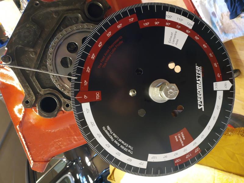
|
|
By capelo - 6 Years Ago
|
Also verified in the exhaust with these values:
162 ° DTDC and 74 ° DTDC that added and divided by two are 118 ° less than the announced 110 ° are 8 °.
As before they came out 10 °, adding the 100 ° of before and these 118 ° added and divided by two are 109 °.
Checking the exhaust opening at 0.050 ".
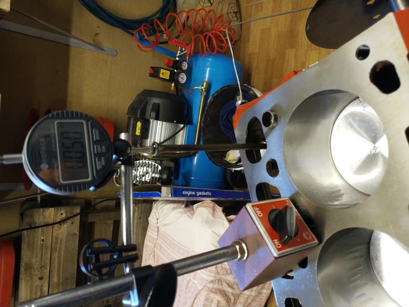 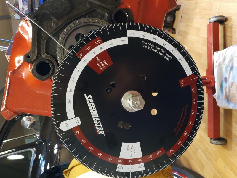
|
|
By Ted - 6 Years Ago
|
Assuming that the crankshaft gear is in the zero position and if targeting for 4-6° of camshaft advance, then you will need to remove and reinstall the crankshaft timing gear so it is in the 4° retard keyway. Be extremely cautious when removing both timing gears in that you do not pry on the pins and instead push the gears forward by prying only on the flats on the chain. Prying on the pins will force the pins forward and cause the chain links to come loose later. Once you have the gears and chain reinstalled in the new position, then recheck both the intake and exhaust lobe centerline numbers and verify that the camshaft is sitting in the 5° advanced position. If it is, you are good to go once you have insured that both the cam thrust and cam gear retaining bolts are properly tightened.
Before removing the degree wheel from the engine, put the crankshaft in the TDC position so that the timing cover, timing pointer, and damper can be installed to verify that the TDC on the damper aligns correctly with the pointer. If it doesn’t, then tweak the pointer so it aligns with the TDC mark on the damper.
|
|
By capelo - 6 Years Ago
|
Ted (4/5/2020)
Assuming that the crankshaft gear is in the zero position and if targeting for 4-6° of camshaft advance, then you will need to remove and reinstall the crankshaft timing gear so it is in the 4° retard keyway. Be extremely cautious when removing both timing gears in that you do not pry on the pins and instead push the gears forward by prying only on the flats on the chain. Prying on the pins will force the pins forward and cause the chain links to come loose later. Once you have the gears and chain reinstalled in the new position, then recheck both the intake and exhaust lobe centerline numbers and verify that the camshaft is sitting in the 5° advanced position. If it is, you are good to go once you have insured that both the cam thrust and cam gear retaining bolts are properly tightened. Before removing the degree wheel from the engine, put the crankshaft in the TDC position so that the timing cover, timing pointer, and damper can be installed to verify that the TDC on the damper aligns correctly with the pointer. If it doesn’t, then tweak the pointer so it aligns with the TDC mark on the damper.
Thanks for the help, I take note and keep moving forward as indicated 👍
|
|
By capelo - 6 Years Ago
|
I have already moved the distribution chain to the mark of R4 and after the test on admission it gives these data:
58 ° ATDC and 152 ° ATDC which added and divided by two give me 105 ° subtracted from the 110 ° result in 5 °.
Measuring 0.050 "in both intake and exhaust, it is 8th before TDC and 53rd before BDC.
Would this be correct to move on?
|
|
By Ted - 6 Years Ago
|
Your numbers look good. If you want to check yourself and/or the camshaft, you can also check the number six cylinder without removing the degree wheel. TDC is the same for both #1 and #6 cylinders. Being as it's an Iskenderian camshaft, I would be comfortable with the numbers off of the #1 cylinder and moving forward if not wanting to pursue this to the next level.
While I typically do not have any issues with the camshaft lifter bank angle when using the Isky camshafts, in a sixteen month period here at the shop I did have three camshafts by other manufacturers that were ground on the wrong lifter bank angle. These can only be found by degreeing in the camshaft by checking cylinders on opposite banks and comparing the numbers. Up to one degree difference between the banks would be tolerable but anymore than that will have you doing further checking. When I find camshafts ground on the incorrect lifter bank angles, I simply send them back to the manufacturer.
|
|
By capelo - 6 Years Ago
|
Do you use any sealant here?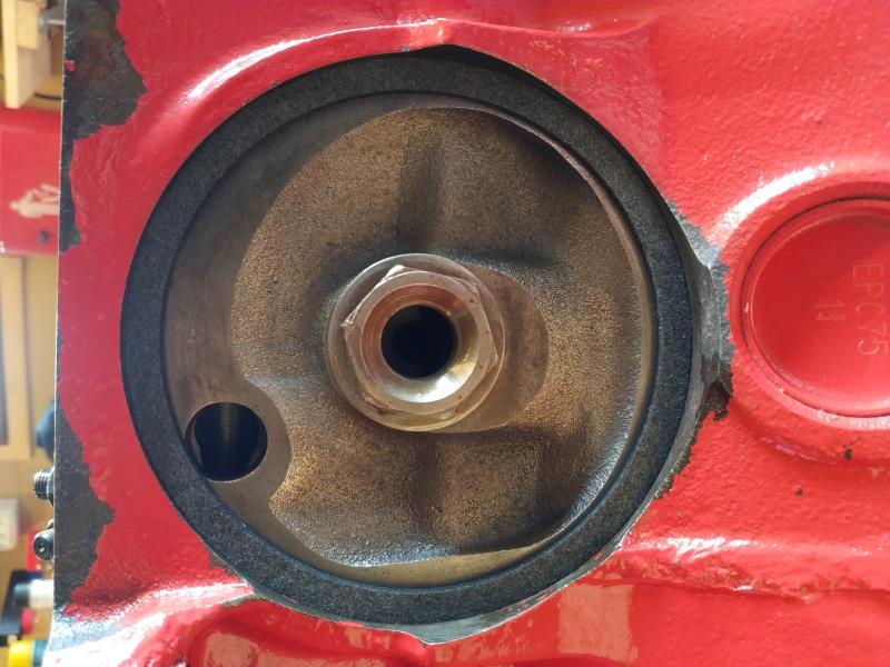
|
|
By capelo - 6 Years Ago
|
Ted (4/5/2020)
Your numbers look good. If you want to check yourself and/or the camshaft, you can also check the number six cylinder without removing the degree wheel. TDC is the same for both #1 and #6 cylinders. Being as it's an Iskenderian camshaft, I would be comfortable with the numbers off of the #1 cylinder and moving forward if not wanting to pursue this to the next level.
While I typically do not have any issues with the camshaft lifter bank angle when using the Isky camshafts, in a sixteen month period here at the shop I did have three camshafts by other manufacturers that were ground on the wrong lifter bank angle. These can only be found by degreeing in the camshaft by checking cylinders on opposite banks and comparing the numbers. Up to one degree difference between the banks would be tolerable but anymore than that will have you doing further checking. When I find camshafts ground on the incorrect lifter bank angles, I simply send them back to the manufacturer.
I keep moving forward thanks 👍
|
|
By Ted - 6 Years Ago
|
capelo (4/6/2020)
Do you use any sealant here? 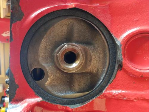
No sealant is required for the gasket.
Are you using a spin on oil filter? If so, then the nut you show in the picture is not correct for the spin on oil filter plate.
|
|
By capelo - 6 Years Ago
|
Ted (4/6/2020)
capelo (4/6/2020)
Do you use any sealant here? No sealant is required for the gasket. Are you using a spin on oil filter? If so, then the nut you show in the picture is not correct for the spin on oil filter plate.
this is what i'm going to use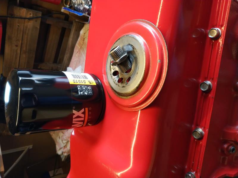
|
|
By Joe-JDC - 6 Years Ago
|
|
I would suggest removing the paint where the oil filter rubber seal will sit when the filter is installed. If you don't, when you go to remove the filter the first time, it will be stuck to the paint and nearly impossible to remove. You may wind up using a punch, or a long screwdriver to stick into the filter to get it off. Punching a hole in the filter will make a mess that can be avoided by removing the paint now. Been there done that. Joe-JDC
|
|
By capelo - 6 Years Ago
|
Joe-JDC (4/6/2020)
I would suggest removing the paint where the oil filter rubber seal will sit when the filter is installed. If you don't, when you go to remove the filter the first time, it will be stuck to the paint and nearly impossible to remove. You may wind up using a punch, or a long screwdriver to stick into the filter to get it off. Punching a hole in the filter will make a mess that can be avoided by removing the paint now. Been there done that. Joe-JDC
Thanks for the advice, that part will be free of paint 👍
|
|
By capelo - 6 Years Ago
|
Well, for today I leave it, tomorrow we continue
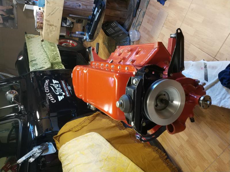
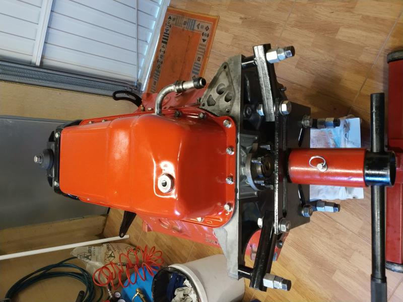 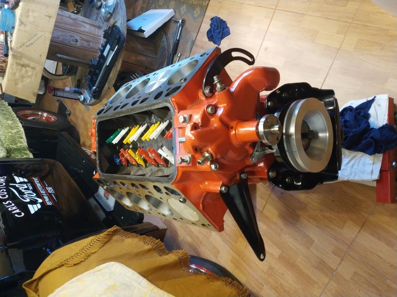 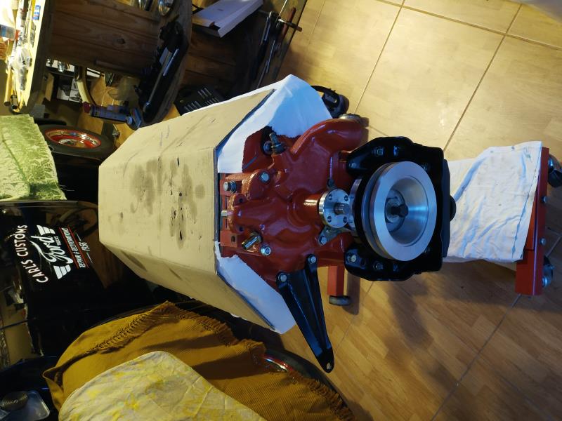
|
|
By capelo - 6 Years Ago
|
Tomorrow I will start mounting the heads. I have bought a new set of ARP bolts from Mummert, it comes with an assembly sheet, but this one, both in the form of tightening and in force and order does not correspond to the previous one read by me here. What is the correct way to act?
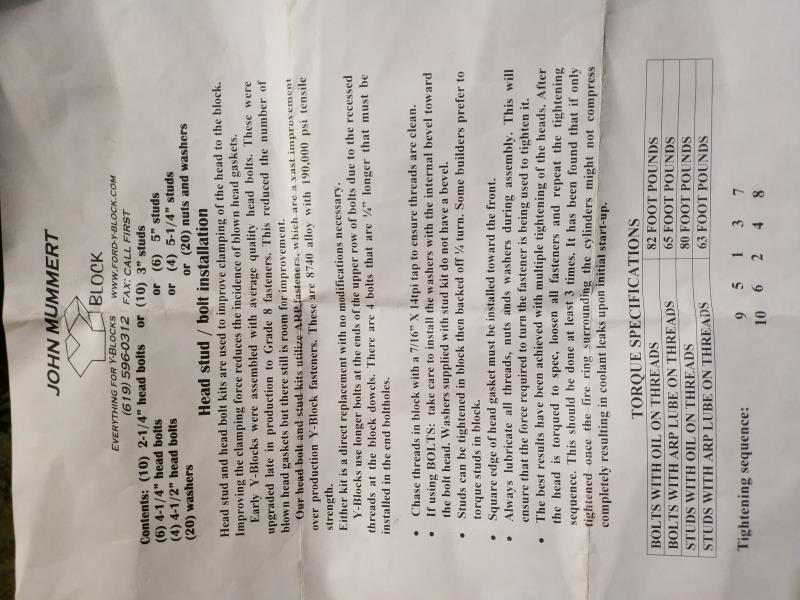
|
|
By capelo - 6 Years Ago
|
|
sorry the tightening order if it is the same
|
|
By Ted - 6 Years Ago
|
For grade eight bolts on the Ford Y, I typically torque them 70# for the short bolts and 75# for the long bolts using oil on the threads. I’ll bring them up in three steps being 35, 50, & 70/75. Bringing the top row to 70 on the third step and then finishing them off at 75# works for me. I’ll use a circular pattern starting at the middle and working outwards on each step. Clockwise (CW) or counter-clockwise (CCW) will not make a difference.
9 5 1 4 8
10 6 2 3 7
Deviations in this work as long as the head bolts are tightened in steps and not to full torque from zero in one step. If someone else has variations in doing this, feel free to chime in.
|
|
By capelo - 6 Years Ago
|
Ted (4/7/2020)
For grade eight bolts on the Ford Y, I typically torque them 70# for the short bolts and 75# for the long bolts using oil on the threads. I’ll bring them up in three steps being 35, 50, & 70/75. Bringing the top row to 70 on the third step and then finishing them off at 75# works for me. I’ll use a circular pattern starting at the middle and working outwards on each step. Clockwise (CW) or counter-clockwise (CCW) will not make a difference. 9 5 1 4 8 10 6 2 3 7 Deviations in this work as long as the head bolts are tightened in steps and not to full torque from zero in one step. If someone else has variations in doing this, feel free to chime in.
Thanks for the advice. The bolts are ARP I guess grade 8 and I have greased the threads like the washers the ARP assembly lubricant. Following that order and that pair is it necessary to repeat it three times as the paper says to seat the joints? I am using "The BEST Gasket"
|
|
By capelo - 6 Years Ago
|
Ted (4/6/2020)
capelo (4/6/2020)
Do you use any sealant here? No sealant is required for the gasket. Are you using a spin on oil filter? If so, then the nut you show in the picture is not correct for the spin on oil filter plate.
about this commented?
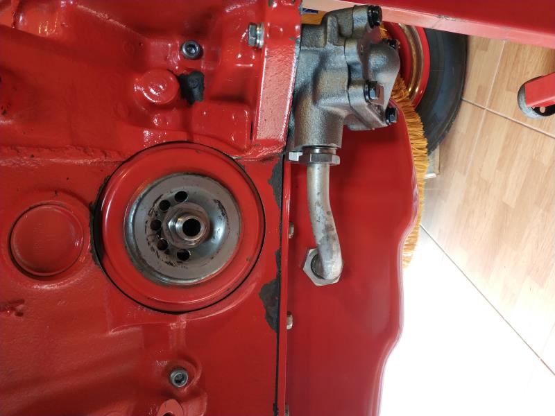
this is correct?
|
|
By Dave C - 6 Years Ago
|
Only thing I would add. If the engine isn't going back in the car the same day, I would come back after it sits over night pull the last number again. What I mean is torque according to what Ted said. Then next day pull that 70/75 one more time. You might be surprised. I have had mine be several pounds loose even using different head gaskets, Felpro, Cometic and even copper..
Do this prior to setting valve lash.
Anyway that is the way I do mine.
Dave
|
|
By capelo - 6 Years Ago
|
Dave C (4/7/2020)
Only thing I would add. If the engine isn't going back in the car the same day, I would come back after it sits over night pull the last number again. What I mean is torque according to what Ted said. Then next day pull that 70/75 one more time. You might be surprised. I have had mine be several pounds loose even using different head gaskets, Felpro, Cometic and even copper.. Do this prior to setting valve lash. Anyway that is the way I do mine. Dave
Ok thaks 👍
|
|
By capelo - 6 Years Ago
|
Today I end it, it already looks like an engine. Intake and cylinder heads, tight.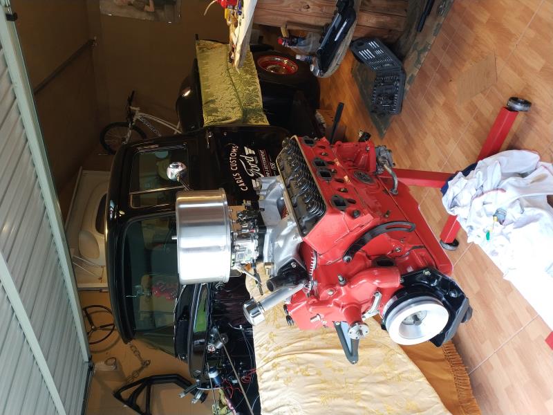 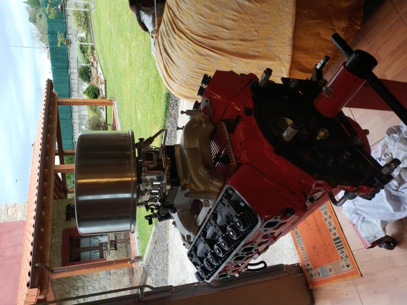
|
|
By capelo - 6 Years Ago
|
Tomorrow I get with them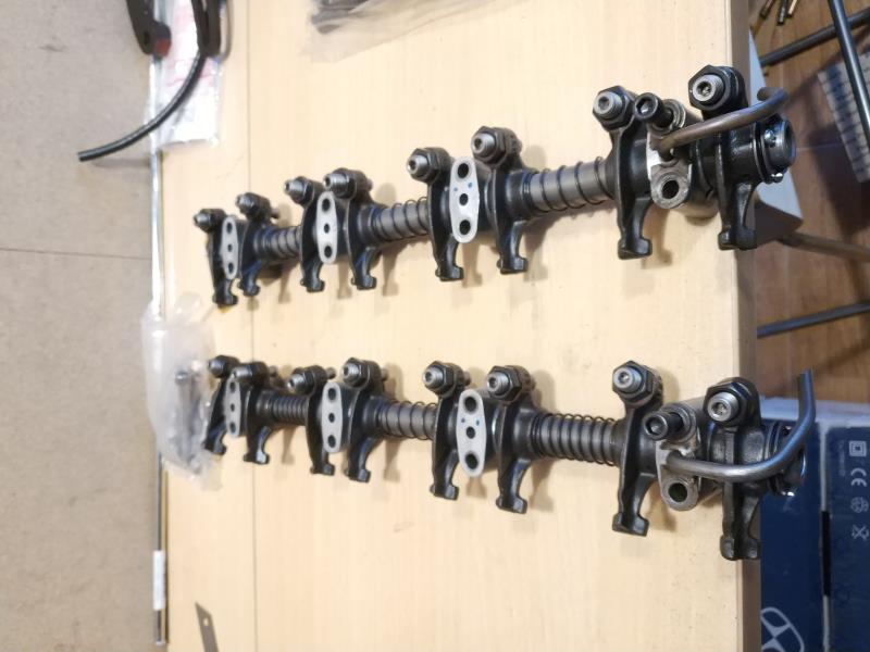
|
|
By MplsMike - 6 Years Ago
|
|
The pictures of the engine are beautiful! How about some pictures of that awesome looking truck in the background?
|
|
By capelo - 6 Years Ago
|
MplsMike (4/7/2020)
The pictures of the engine are beautiful! How about some pictures of that awesome looking truck in the background?
Thanks 👍
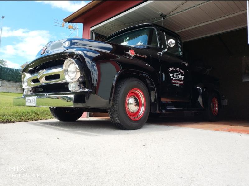 
|
|
By BamaBob - 6 Years Ago
|
capelo (4/7/2020)
Tomorrow I get with them
|
|
By BamaBob - 6 Years Ago
|
It appears you have the rocker arms oil overflow tube on the right side(passenger side) on the wrong end of the arm. It should be on the front end where it goes in the hole to help oil the camshaft chain and gears. All the rocker arms will have to be turned around in order for the oil holes in the rocker arm shaft to line up. It is crucial that they do line up properly.
On second look at the picture, it appears that both of the rocker sets are backwards. Does it appear this way to anyone else?
|
|
By charliemccraney - 6 Years Ago
|
|
They look correct. They are assembled the same way. When oriented as they would be when installed, the driver's side tube will be at the rear while the passenger's side tube will be at the front.
|
|
By capelo - 6 Years Ago
|
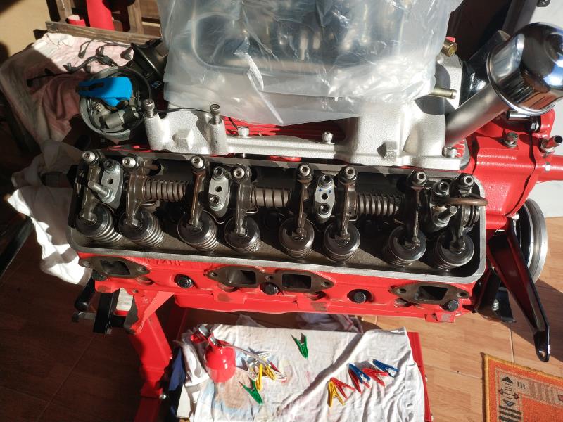 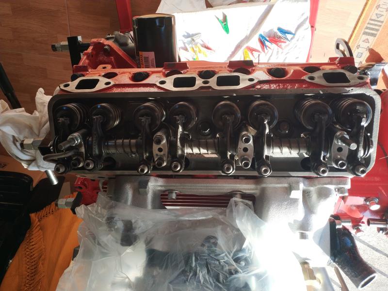 un uncharliemccraney (4/8/2020)
They look correct. They are assembled the same way. When oriented as they would be when installed, the driver's side tube will be at the rear while the passenger's side tube will be at the front.
|
|
By capelo - 6 Years Ago
|
None of them is correct?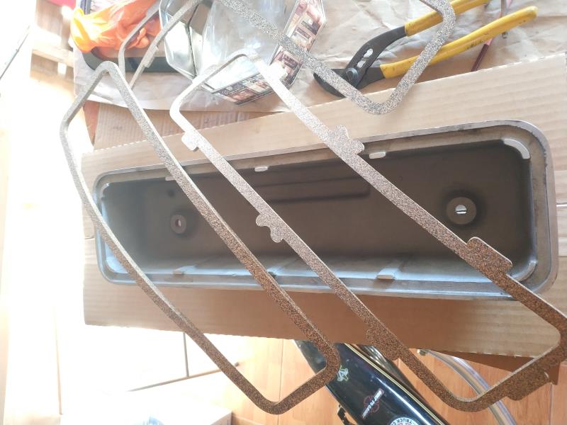 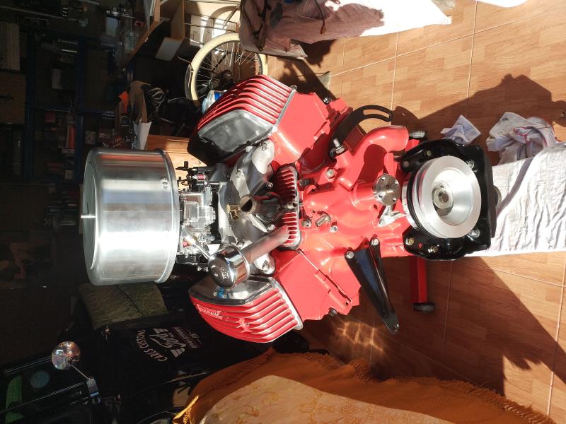
|
|
By capelo - 6 Years Ago
|
I have a space problem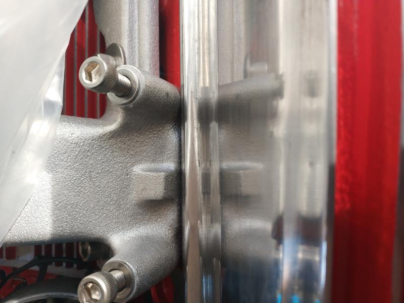 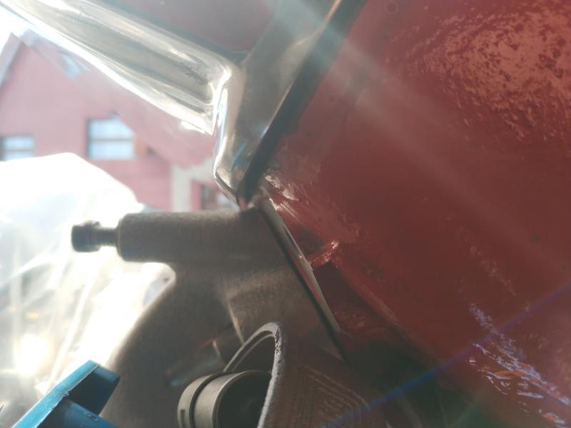
|
|
By capelo - 6 Years Ago
|
I want to leave the distributor open for the engine start, I have in the Damper 16 ° before the top dead center.
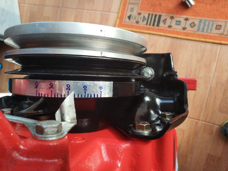
Now, as the distributor has to be exactly, the line that can be seen by pencil would be the cable of the number 1 cylinder. In that position, how should the points be?
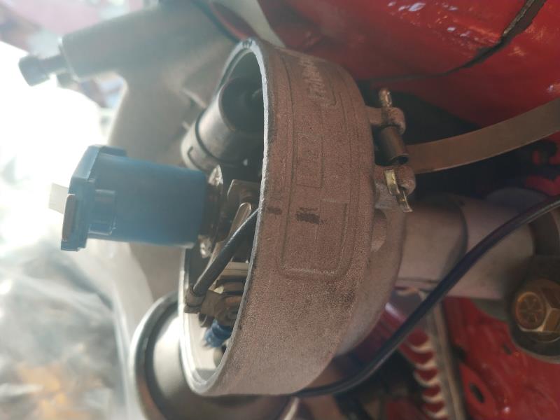 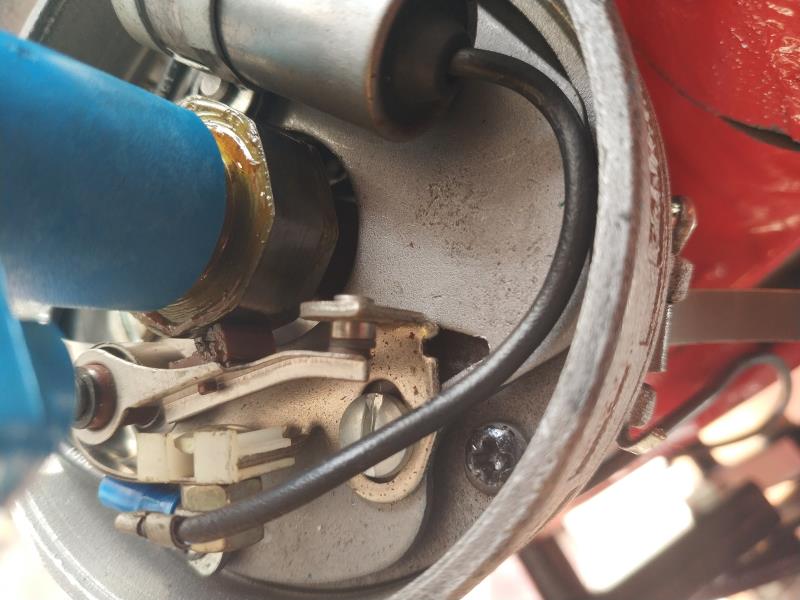
|
|
By charliemccraney - 6 Years Ago
|
Regarding the valve cover gaskets:
Sometimes aftermarket covers don't fit the gaskets correctly. I've used a Dremel with a cut off wheel to widen the gap so that the gaskets fit correctly. Once they fit, use adhesive to glue the gasket to the valve cover, to ease installation.
You can trim the tabs off of the gaskets that have them, to fit your valve covers.
Regarding the clearance to the intake:
Just about the same story. Place them on the head and mark the areas that need clearance then use a Dremel to remove material until it fits. Use an old gasket, if available, while doing this so that the valve cover is sitting at the correct height, so that only the amount of materiel that needs to be removed is removed.
If the gasket was not in place when you took the picture. put it in place and see if the problem still exists. Note that a new gasket will compress when tightened so ensure that clearance is adequate for that.
A die grinder will probably work better for these modifications but most people in this hobby have a Dremel or similar tool and it works, just more slowly.
|
|
By capelo - 6 Years Ago
|
charliemccraney (4/8/2020)
Regarding the valve cover gaskets: Sometimes aftermarket covers don't fit the gaskets correctly. I've used a Dremel with a cut off wheel to widen the gap so that the gaskets fit correctly. Once they fit, use adhesive to glue the gasket to the valve cover, to ease installation. You can trim the tabs off of the gaskets that have them, to fit your valve covers. Regarding the clearance to the intake: Just about the same story. Place them on the head and mark the areas that need clearance then use a Dremel to remove material until it fits. Use an old gasket, if available, while doing this so that the valve cover is sitting at the correct height, so that only the amount of materiel that needs to be removed is removed. If the gasket was not in place when you took the picture. put it in place and see if the problem still exists. Note that a new gasket will compress when tightened so ensure that ensure that clearance is adequate for that. A die grinder will probably work better for these modifications but most people in this hobby have a Dremel or similar tool and it works, just more slowly.
Thanks for the tips, I take note 👍
|
|
By Ted - 6 Years Ago
|
|
capelo (4/8/2020)
I want to leave the distributor open for the engine start, I have in the Damper 16 ° before the top dead center.
Now, as the distributor has to be exactly, the line that can be seen by pencil would be the cable of the number 1 cylinder. In that position, how should the points be?
For first starts, my preference is to put the damper at 20-25 BTDC and then time the distributor accordingly. With the breaker point ignition and with the rotor in the neighborhood of coming up to the #1 post in the distributor cap, turn the distributor housing clockwise to where the breaker points just crack open. The rotor should be pointing at the #1 post in the cap. You can now tighten the distributor. I would much rather have the timing liberally advanced for first starts rather than be retarded which can cause the engine to belch, cough, or spit fire when attempting to do those first starts. Once the engine is up and running and the camshaft is broken in, you can check the timing with a light and adjust accordingly.
|
|
By capelo - 6 Years Ago
|
Ted (4/8/2020)
capelo (4/8/2020)
I want to leave the distributor open for the engine start, I have in the Damper 16 ° before the top dead center.
Now, as the distributor has to be exactly, the line that can be seen by pencil would be the cable of the number 1 cylinder. In that position, how should the points be?For first starts, my preference is to put the damper at 20-25 BTDC and then time the distributor accordingly. With the breaker point ignition and with the rotor in the neighborhood of coming up to the #1 post in the distributor cap, turn the distributor housing clockwise to where the breaker points just crack open. The rotor should be pointing at the #1 post in the cap. You can now tighten the distributor. I would much rather have the timing liberally advanced for first starts rather than be retarded which can cause the engine to belch, cough, or spit fire when attempting to do those first starts. Once the engine is up and running and the camshaft is broken in, you can check the timing with a light and adjust accordingly.
Ok, I note, at that time described, the dots open and close just before aiming for the cylinder 1 pole, is this correct? . At those 20 ° BTDC, is the dealer with the spots open or is he already aiming for the cap post on cylinder 1?
|
|
By Ted - 6 Years Ago
|
capelo (4/9/2020)
Ok, I note, at that time described, the dots open and close just before aiming for the cylinder 1 pole, is this correct? . At those 20 ° BTDC, is the dealer with the spots open or is he already aiming for the cap post on cylinder 1?
Hopefully this gets through the English to Spanish conversion without getting too distorted.
The rotor pointing at the #1 post in the distributor cap is a secondary effect of where the rotor is aimed as a result of the points just starting to open. That’s assuming that the distributor is stabbed in the block so it will have the rotor aimed at the right spot in the cap. It doesn’t matter where the #1 wire is in the cap as long as the rotor is pointing to that particular spot once you have the distributor housing adjusted to that spot where the breaker points have just started to open.
Because the rotor normally turns in a CCW direction, you will need to turn the distributor housing in a CW direction until the breaker points just start to open and no more. It is when the points just crack open as to when the current to the spark plugs is generated. The more the distributor is turned past that point where the points just opened, then the more the timing will be retarded. If the rotor is not pointing at the #1 post in the cap and instead is pointing to another cylinder when the breaker points just crack open, then either the housing or the distributor shaft will need to be turned accordingly to make that happen.
|
|
By capelo - 6 Years Ago
|
Ted (4/9/2020)
capelo (4/9/2020)
Ok, I note, at that time described, the dots open and close just before aiming for the cylinder 1 pole, is this correct? . At those 20 ° BTDC, is the dealer with the spots open or is he already aiming for the cap post on cylinder 1? Hopefully this gets through the English to Spanish conversion without getting too distorted. The rotor pointing at the #1 post in the distributor cap is a secondary effect of where the rotor is aimed as a result of the points just starting to open. That’s assuming that the distributor is stabbed in the block so it will have the rotor aimed at the right spot in the cap. It doesn’t matter where the #1 wire is in the cap as long as the rotor is pointing to that particular spot once you have the distributor housing adjusted to that spot where the breaker points have just started to open. Because the rotor normally turns in a CCW direction, you will need to turn the distributor housing in a CW direction until the breaker points just start to open and no more. It is when the points just crack open as to when the current to the spark plugs is generated. The more the distributor is turned past that point where the points just opened, then the more the timing will be retarded. If the rotor is not pointing at the #1 post in the cap and instead is pointing to another cylinder when the breaker points just crack open, then either the housing or the distributor shaft will need to be turned accordingly to make that happen.
I don't want to mess things up a lot at this point, but I do want to do the right thing. I think I understand the explanation, I have the mark at 20 ° BTDC. Well the distributor, I have it in place with the rotor pointed at cylinder 1, I turn the housing clockwise towards cylinder 2 and when the points begin to open is where I lock the housing.
|
|
By capelo - 6 Years Ago
|
Following Ted's articles
http://www.eatonbalancing.com/blog/2009/06/12/spark-plug-indexing/
http://www.eatonbalancing.com/blog/2009/06/11/spark-plug-side-gapping/
I have acted accordingly

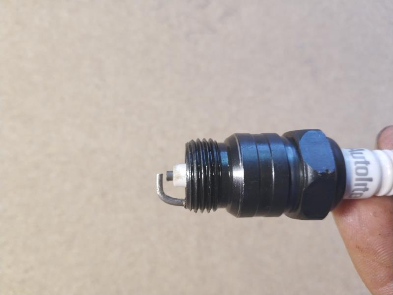
|
|
By capelo - 6 Years Ago
|
A little help
|
|
By MplsMike - 6 Years Ago
|
|
That looks like a Boddingtons to me. Enjoy!!
|
|
By capelo - 6 Years Ago
|
There is less left to return it to the truck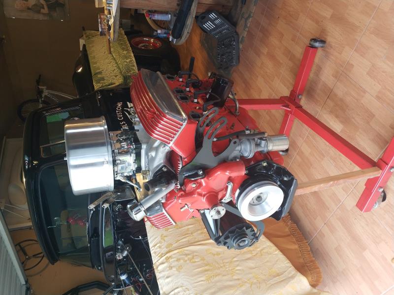 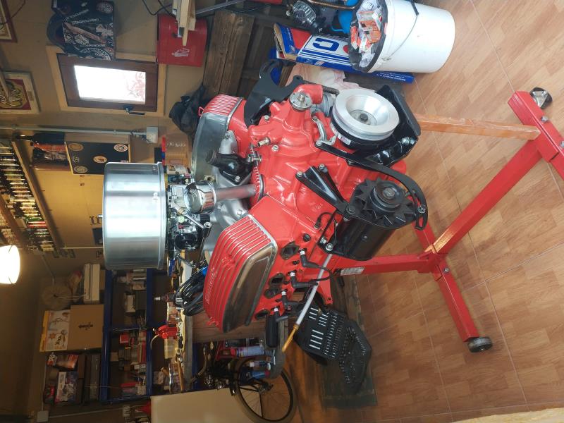 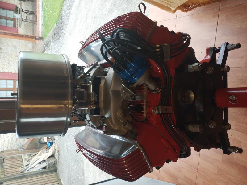
|
|
By capelo - 6 Years Ago
|
MplsMike (4/9/2020)
That looks like a Boddingtons to me. Enjoy!!
The same, friend👍
|
|
By Ted - 6 Years Ago
|
capelo (4/9/2020)
I don't want to mess things up a lot at this point, but I do want to do the right thing. I think I understand the explanation, I have the mark at 20 ° BTDC. Well the distributor, I have it in place with the rotor pointed at cylinder 1, I turn the housing clockwise towards cylinder 2 and when the points begin to open is where I lock the housing.
As long as the rotor is pointing at the #1 post in the distributor cap when the breaker points are just opening, you will be good.
|
|
By capelo - 6 Years Ago
|
Ted (4/9/2020)
capelo (4/9/2020)
I don't want to mess things up a lot at this point, but I do want to do the right thing. I think I understand the explanation, I have the mark at 20 ° BTDC. Well the distributor, I have it in place with the rotor pointed at cylinder 1, I turn the housing clockwise towards cylinder 2 and when the points begin to open is where I lock the housing. As long as the rotor is pointing at the #1 post in the distributor cap when the breaker points are just opening, you will be good.
Ok
|
|
By kevink1955 - 6 Years Ago
|
Your build looks great, you are paying attention to many details that are often missed, good luck with the first run. Just be sure to follow the cam break in instructions for the first run and your engine will have a long life
I am glad Ted keeps emphasizing watching for the points to OPEN, while the rotor is heading for the #1 terminal
Many people think the coil generates spark when the points close, thats a wrong assumption, the spark is generated when the points open and the magnetic field in the coil collapses
I have timed many engines the way Ted described and they always start first try
|
|
By capelo - 6 Years Ago
|
Well, I only have to make the fuel line from the pump to the carb to finish and to put the engine in place. after that I will fill the motor with Valvoline oil to which I will add 4oz of ZDDP.
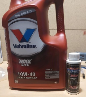
I will turn the oil pump with an old distributor until the entire circuit is filled with pressure. I'll fill the carburetor. What I don't know is if I should connect the vacuum to the distributor as well as the PCV valve? the carb is new a Summit "SUM-M08750VS" do you know if I have to do something for the initial start? I also have the question of whether to do the initial boot already, I ask it because due to the confinement state in Covid19 I will not be able to run with it in a long time, that would be a problem?
|
|
By marvh - 6 Years Ago
|
For doing the Y with that distributor in a dark hole I disconnect the wire from the coil to distributor and hook a lead from an ohm meter to the wire and other lead to ground then watch when the contact opens.
I have done this for many years tuning two cycle golf cart engines. On golf carts you have to adjust point gap opening as well for correct timing so engine starts easily in clockwise or counter clockwise rotation
|
|
By ian57tbird - 6 Years Ago
|
Yes that will work for timing it.
You should have the distributor cap off when doing this to make sure you are opening the points while the rotor is in the correct position. (Just coming up to number 1 position, but before the points are starting to open)
An easier way to set the timing with points is to leave everything connected (Except for the cap off for the same reason) and attach a 12v test light to the coil terminal that goes to the distributor. The other end of that test light goes to ground. Turn the ignition to on in your car. The light will come on the instant the points start to open. You can also use a volt meter but I prefer the light as you don't have to concentrate on looking at a gauge. Just remember you need to be rotating the distributor the opposite direction to the way the rotor spins when static timing an engine.
I only ever rotate the engine up to the desired timing mark in the direction that it would normally turn. That way it also allows for any slack in the timing chain. Unlikely you will have any slack though with a fresh engine.
Static timing with a light or volt meter is as precise as a timing light, but just takes longer.
|
|
By capelo - 6 Years Ago
|
|
thanks guys for the comments👍
|
|
By Ted - 6 Years Ago
|
capelo (4/9/2020)
....What I don't know is if I should connect the vacuum to the distributor as well as the PCV valve? the carb is new a Summit "SUM-M08750VS" do you know if I have to do something for the initial start? I also have the question of whether to do the initial boot already, I ask it because due to the confinement state in Covid19 I will not be able to run with it in a long time, that would be a problem?
Be sure only fresh fuel is in the gas tank of the vehicle. Old fuel creates its own set of problems.
Leave the vacuum advance disconnected for the time being. The PCV valve can be hooked up.
Disable the choke for the first start. Put some fuel in the carburetor bowls before attempting to start the engine for the first time. This can be performed by using a very small funnel and slowly pouring fuel into each carb vent. Just prior to doing the first start, work the throttle to full open and put 2-3 shots of fuel into the manifold. Let that fuel sit for about ten seconds so it can vaporize some before attempting the first start. Assuming the ignition timing is in the ball park, the engine will immediately fire up at which point you will want to bring the rpm up to 2000-2200 for the camshaft break in. Twenty minutes of engine run in proves to be sufficient in most cases.
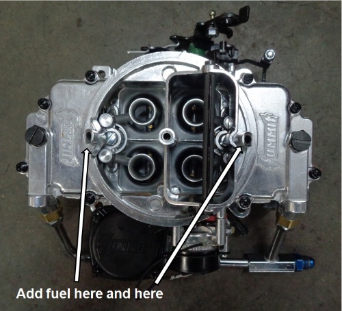
|
|
By capelo - 6 Years Ago
|
Ted (4/11/2020)
capelo (4/9/2020)
....What I don't know is if I should connect the vacuum to the distributor as well as the PCV valve? the carb is new a Summit "SUM-M08750VS" do you know if I have to do something for the initial start? I also have the question of whether to do the initial boot already, I ask it because due to the confinement state in Covid19 I will not be able to run with it in a long time, that would be a problem? Be sure only fresh fuel is in the gas tank of the vehicle. Old fuel creates its own set of problems. Leave the vacuum advance disconnected for the time being. The PCV valve can be hooked up. Disable the choke for the first start. Put some fuel in the carburetor bowls before attempting to start the engine for the first time. This can be performed by using a very small funnel and slowly pouring fuel into each carb vent. Just prior to doing the first start, work the throttle to full open and put 2-3 shots of fuel into the manifold. Let that fuel sit for about ten seconds so it can vaporize some before attempting the first start. Assuming the ignition timing is in the ball park, the engine will immediately fire up at which point you will want to bring the rpm up to 2000-2200 for the camshaft break in. Twenty minutes of engine run in proves to be sufficient in most cases.
Thanks for the advice, I take note. I was filling the engine with oil and I had a big doubt, it is Valvoline 10w40, but I have noticed that it puts synthetic I have added ZDDP, but is it adequate?
|
|
By capelo - 6 Years Ago
|
For today I leave it, tomorrow take care of yourselves 💪
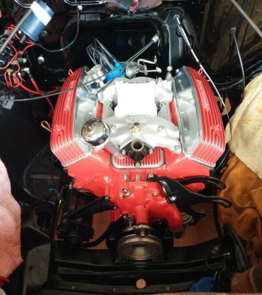
|
|
By Ted - 6 Years Ago
|
capelo (4/11/2020)
Thanks for the advice, I take note. I was filling the engine with oil and I had a big doubt, it is Valvoline 10w40, but I have noticed that it puts synthetic I have added ZDDP, but is it adequate?
For first starts, a conventional grade of oil is recommended and not synthetic oil. The reduced friction attributes of synthetic oil does minimize the friction on the new cylinder wall finish thus preventing the rings from seating in properly. If the new cylinder wall finish glazes over as a result of non-friction, then the rings will take an abnormally amount of time to seat to the freshly finished cylinder walls.
While attempting not to be an alarmist, I have seen instances on new engines where the cylinder walls glazed over so completely as to prevent the rings from ever seating. Those engines had to be torn completely down with the cylinder walls being honed again to get a cylinder wall finish that’s conducive to seating in the rings.
|
|
By capelo - 6 Years Ago
|
Ted (4/13/2020)
capelo (4/11/2020)
Thanks for the advice, I take note. I was filling the engine with oil and I had a big doubt, it is Valvoline 10w40, but I have noticed that it puts synthetic I have added ZDDP, but is it adequate? For first starts, a conventional grade of oil is recommended and not synthetic oil. The reduced friction attributes of synthetic oil does minimize the friction on the new cylinder wall finish thus preventing the rings from seating in properly. If the new cylinder wall finish glazes over as a result of non-friction, then the rings will take an abnormally amount of time to seat to the freshly finished cylinder walls. While attempting not to be an alarmist, I have seen instances on new engines where the cylinder walls glazed over so completely as to prevent the rings from ever seating. Those engines had to be torn completely down with the cylinder walls being honed again to get a cylinder wall finish that’s conducive to seating in the rings.
That sounds like a big problem, what do I have to do now to fix it, that oil do I have to throw away?
|
|
By capelo - 6 Years Ago
|
This is what I have used

|
|
By Lord Gaga - 6 Years Ago
|
|
Recycle it OR use it in you your lawnmower.
|
|
By Ted - 6 Years Ago
|
capelo (4/13/2020)
Ted (4/13/2020)
capelo (4/11/2020)
Thanks for the advice, I take note. I was filling the engine with oil and I had a big doubt, it is Valvoline 10w40, but I have noticed that it puts synthetic I have added ZDDP, but is it adequate? For first starts, a conventional grade of oil is recommended and not synthetic oil. The reduced friction attributes of synthetic oil does minimize the friction on the new cylinder wall finish thus preventing the rings from seating in properly. If the new cylinder wall finish glazes over as a result of non-friction, then the rings will take an abnormally amount of time to seat to the freshly finished cylinder walls. While attempting not to be an alarmist, I have seen instances on new engines where the cylinder walls glazed over so completely as to prevent the rings from ever seating. Those engines had to be torn completely down with the cylinder walls being honed again to get a cylinder wall finish that’s conducive to seating in the rings. That sounds like a big problem, what do I have to do now to fix it, that oil do I have to throw away?
Just put the synthetic oil to the side and use it much later after the engine is thoroughly broken in. If you experience oil leaks when you go back to the synthetic oil later, then just switch back to the conventional grade oil. For engines with low mileage (ie: less than 75K miles), do not use oils with ‘High Mileage’ on their labels as those contain additives that soften and swell up the engine seals.
Here’s the oil I use for first start ups and break in.
|
|
By capelo - 6 Years Ago
|
Thank you, I will take that oil out and save it for another time, any rest will be left, is that a problem? He did not find that oil that he advises, I find a semi-synthetic, 100% mineral no.
|
|
By capelo - 6 Years Ago
|
I have found two bottles of this oil at home
It takes time at home but I do not know if it is valid, since I cannot find where it indicates whether it is mineral or synthetic, someone knows it
|
|
By Ted - 6 Years Ago
|
Any residual oil remaining in the engine when draining the synthetic oil is not expected to create any problems.
I would shy away from any 20W-50 oil for engines that do not have the additional bearing clearances built into them or is the result of high mileage wear. Here is another suggestion for a suitable oil for your engine for break in purposes. Be sure to add another bottle of zinc/phosphate additive to the oil for break in purposes.
|
|
By capelo - 6 Years Ago
|
Ted (4/15/2020)
Any residual oil remaining in the engine when draining the synthetic oil is not expected to create any problems. I would shy away from any 20W-50 oil for engines that do not have the additional bearing clearances built into them or is the result of high mileage wear. Here is another suggestion for a suitable oil for your engine for break in purposes. Be sure to add another bottle of zinc/phosphate additive to the oil for break in purposes.
Here I can't find any mineral-based 10w40 oil, with that graduation only semi-synthetic. Can i find 15w 40 mineral could this work?
|
|
By Ted - 6 Years Ago
|
capelo (4/15/2020)
Here I can't find any mineral-based 10w40 oil, with that graduation only semi-synthetic. Can i find 15w 40 mineral could this work?
Yes.
|
|
By MplsMike - 6 Years Ago
|
|
Capelo, it’s been a week since your last post. We are worried about you! I hope you are still making good progress.
|
|
By capelo - 6 Years Ago
|
MplsMike (4/22/2020)
Capelo, it’s been a week since your last post. We are worried about you! I hope you are still making good progress.
Thanks for the interest, everything is fine here. I have no news, I have everything ready waiting for the heating hoses to arrive so that I can fill the cooling circuit and then start the engine. I am also a little worried about the connection of the fuel line from the pump to the carb, when I filled the carb I lost some fuel, because of the carb joint I dried it, I squeezed but I don't know when there is pressure if it will lose again what it would be a serious problem 😏
|
|
By capelo - 6 Years Ago
|
with this connection is the one with which I am not very convinced.
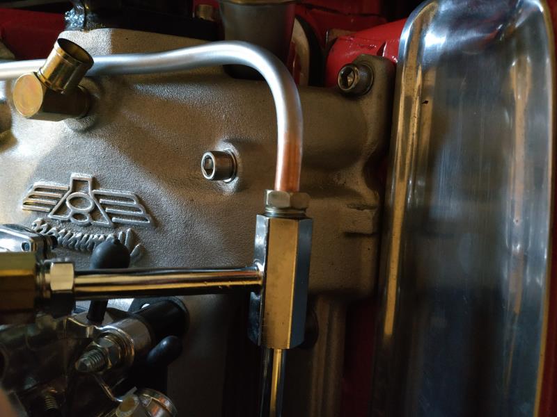
The one on the left is the original flare that is double and I could only make it simple that you see on the left.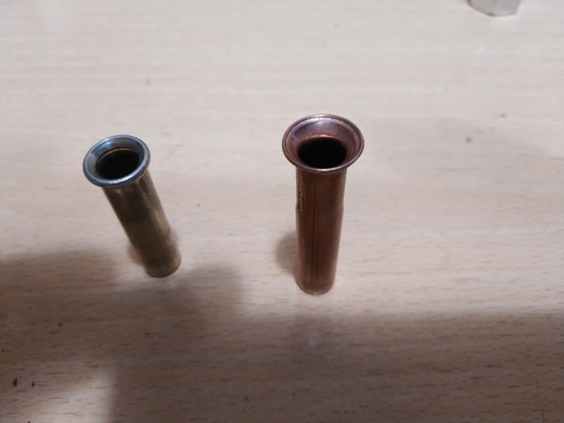
I am also looking at another option.
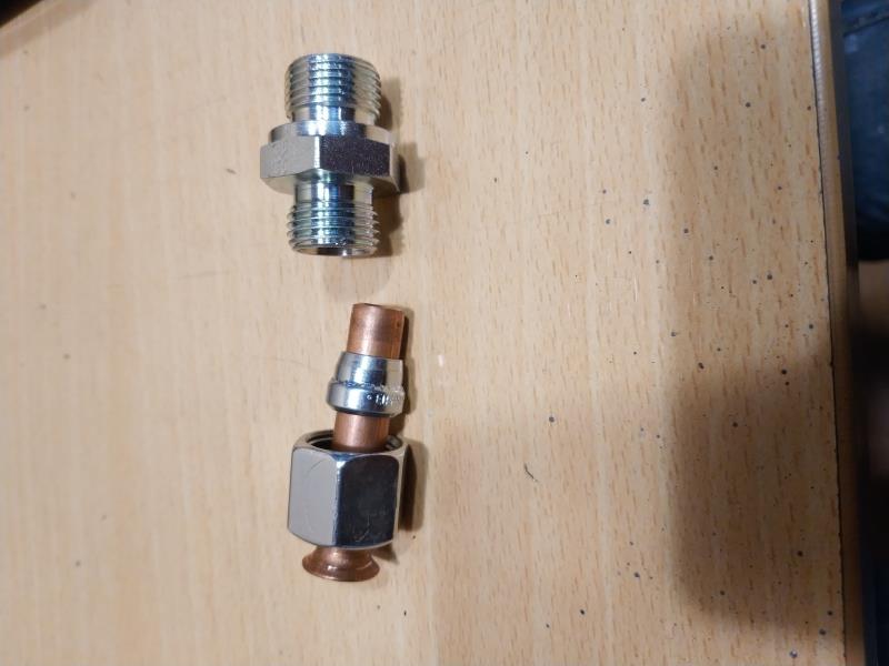
I am also looking at another option.
|
|
By charliemccraney - 6 Years Ago
|
|
A single flare is ok for fuel line.
|
|
By Ted - 6 Years Ago
|
I’ll have to disagree with Charlie regarding the use of a single flare end on the fuel line. And I also have an issue with using copper instead of steel for fuel lines. I’ve been both ways early on (teenager) and the single flare ends to have a tendency to split at the flare opening while copper is seamed tubing which also has a tendency to crack along the seams when vibration is present.
A fire as a result of a broken or cracked line would not make for a happy day. My recommendation is a steel line with the appropriate double flare. The quality of the flaring tool also makes a difference. If you need some kind of pictorial showing how to do double flares, just let me know and I’ll see what I can work up.
|
|
By capelo - 6 Years Ago
|
Ted (4/25/2020)
I’ll have to disagree with Charlie regarding the use of a single flare end on the fuel line. And I also have an issue with using copper instead of steel for fuel lines. I’ve been both ways early on (teenager) and the single flare ends to have a tendency to split at the flare opening while copper is seamed tubing which also has a tendency to crack along the seams when vibration is present. A fire as a result of a broken or cracked line would not make for a happy day. My recommendation is a steel line with the appropriate double flare. The quality of the flaring tool also makes a difference. If you need some kind of pictorial showing how to do double flares, just let me know and I’ll see what I can work up.
thanks for the comments, an illustration never hurts. A question, how big is the thread of the image connection?
|
|
By Ted - 6 Years Ago
|
capelo (4/25/2020)
thanks for the comments, an illustration never hurts. A question, how big is the thread of the image connection?
The size designation for the fitting that goes into the Summit fuel line is ‘3/8” Inverted Flare’. A normal straight threaded fitting will not work as it does need a bevel on the fitting to match the bevel within the fuel line so insure a positive seal.
|
|
By Ted - 6 Years Ago
|
TUTORIAL FOR DOUBLE FLARING TUBING
Remove burrs from inside of cut end of tubing
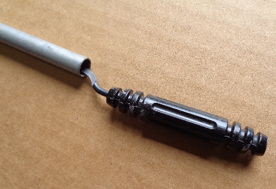
Here’s the double flaring tool as a kit for the various tubing sizes
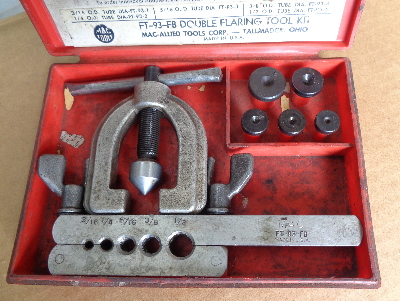
Select the appropriate adapter. In your particular instance, use the one labeled ‘3/8’
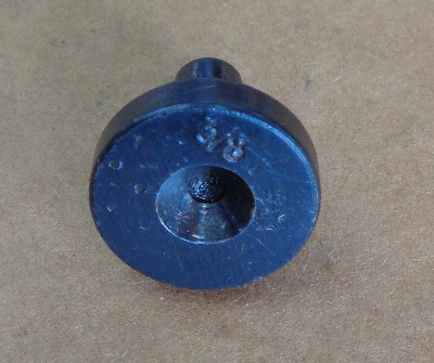
Install the tubing end in the flaring bar so the end of it protrudes to the level of the first ledge on the adapter. Tighten the bar so the tube does not slip.
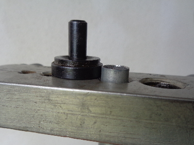
Put oil or some kind of lubricant on both the stem side of the adapter and at the end of the tube in the flaring bar.
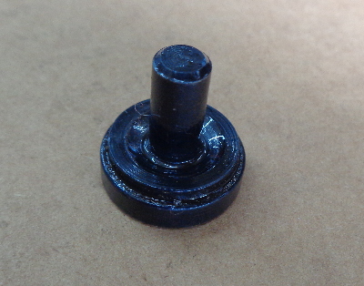
Place the adapter with the stem inside the tube.
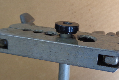
Center the flaring yoke over the adapter.
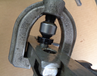
Turn the feed screw on the yoke until the adapter is flush with the surface of the flaring bar.
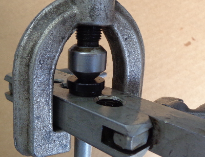
Remove the yoke and examine the partially flared end of the tubing to insure there is no splitting occurring and it's even all the way around.
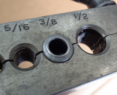
Reinstall the flaring yoke and center it over the end of the tubing.
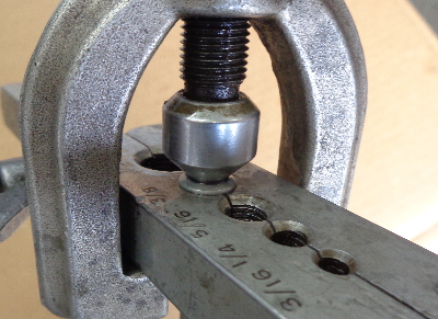
Again turn the yoke feed screw until it as tight as you can get it doing it by hand.
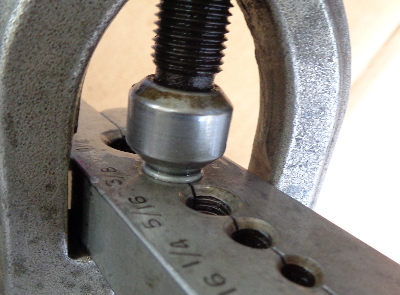
Remove the flaring yoke and examine the completed flare. If it looks like it does not have a surface that’s flattened out enough, reinstall the yoke again and screw it down tighter.
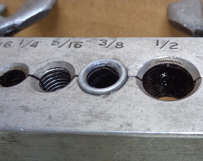
Remove the completed tubing from the flaring bar and examine it for any defects. At this point it is expected to good to go.
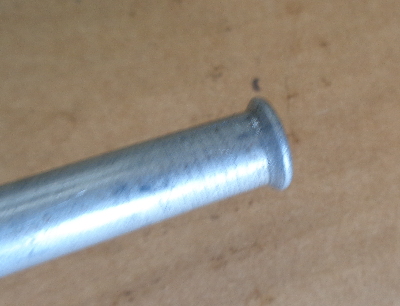
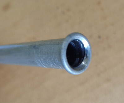
|
|
By kevink1955 - 6 Years Ago
|
Now put the OH CRAP flare nut on the tube.
Please remember the flare nut MUST be on the tube BEFORE you do the flare if there are any bends or the other end has already been flared.
Ask me how I know this Lol
Great Tutorial TED as always
|
|
By capelo - 6 Years Ago
|
Doing a test:
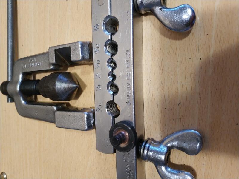
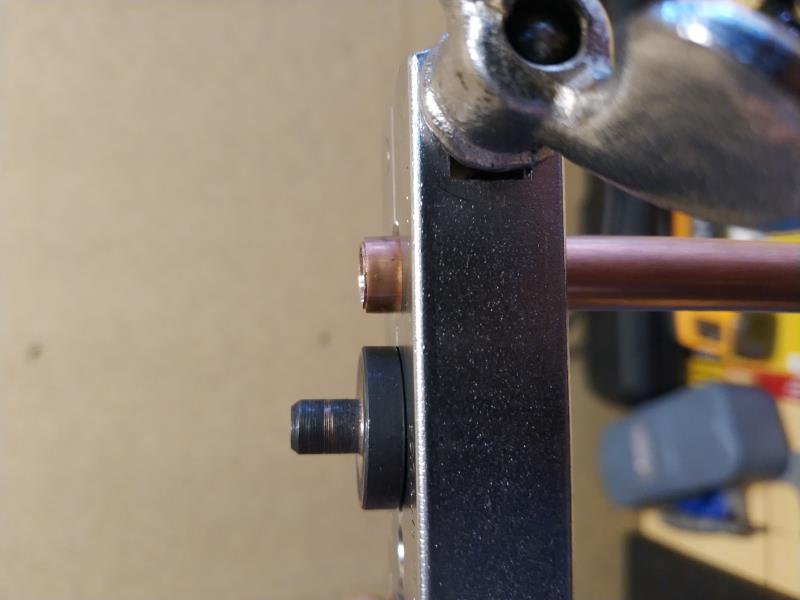 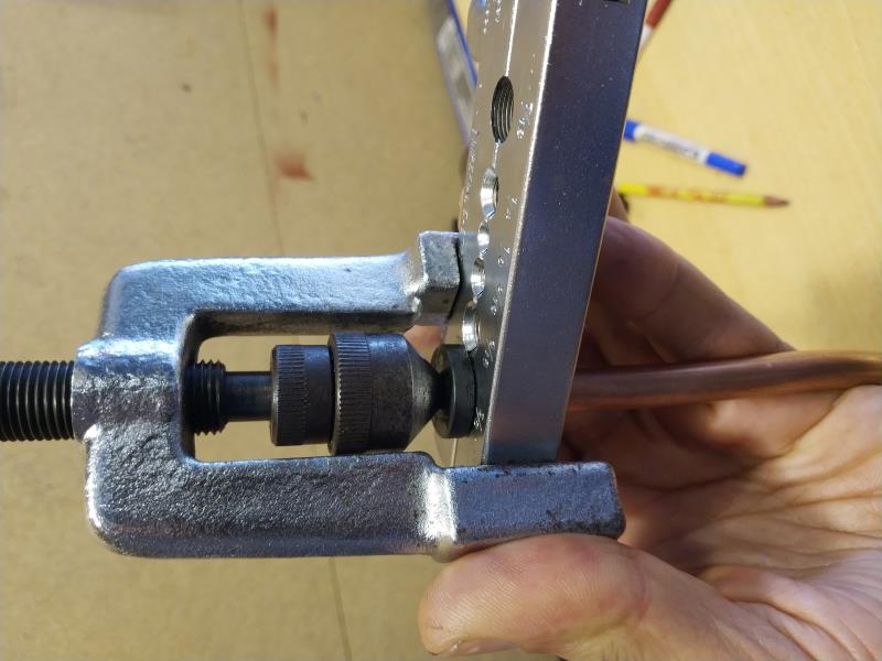 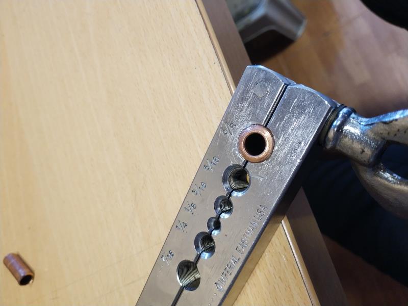
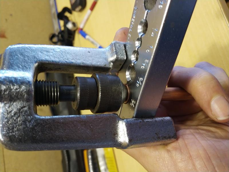 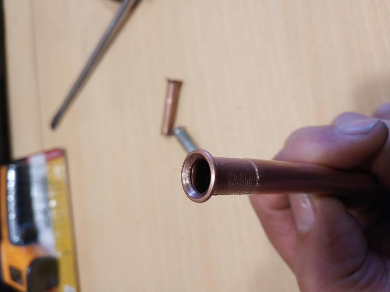
|
|
By 57RancheroJim - 6 Years Ago
|
Is that copper or nicopp?
|
|
By DryLakesRacer - 6 Years Ago
|
I have made hundreds of single and double flares with the tool shown and even with one which included rollers and tho they worked I was never happy with them.
3 years ago I purchased an Eastwood flaring tool, there are others too probably by the same manufacturer, and could never be happier. It handles up to 3/8" tubing and every end is perfect with 2 pulls of the handle and a click of the tool head. It can also put a "bulb" end with a little practice. Yes it was over $100 and since my son has done his complete brake and fuel system and I have done a rear end change and disc brakes I can say it was worth every penny. I'd show a photo but it's at his garage right now and are ez to find on the Internet.
Over the years learning to do things on my own and purchasing good quality tools that will last a guy time me a life time has not always been possible but was done as the need arised. I don't a shop or make any profit but sure am happy when thing go right because the correct tool was there to use.
We started using nicopp and so far been pleased.
|
|
By capelo - 6 Years Ago
|
57RancheroJim (4/26/2020)
Is that copper or nicopp?
I made it with copper since I had nothing else
|
|
By capelo - 6 Years Ago
|
DryLakesRacer (4/26/2020)
I have made hundreds of single and double flares with the tool shown and even with one which included rollers and tho they worked I was never happy with them. 3 years ago I purchased an Eastwood flaring tool, there are others too probably by the same manufacturer, and could never be happier. It handles up to 3/8" tubing and every end is perfect with 2 pulls of the handle and a click of the tool head. It can also put a "bulb" end with a little practice. Yes it was over $100 and since my son has done his complete brake and fuel system and I have done a rear end change and disc brakes I can say it was worth every penny. I'd show a photo but it's at his garage right now and are ez to find on the Internet. Over the years learning to do things on my own and purchasing good quality tools that will last a guy time me a life time has not always been possible but was done as the need arised. I don't a shop or make any profit but sure am happy when thing go right because the correct tool was there to use. We started using nicopp and so far been pleased.
thanks for the comment
|
|
By capelo - 6 Years Ago
|
|
Are there various diameters in 3/8 ...? I have measured the connection of the carburetor and it gives me 15.6mm and another that I have supposedly also 3/8 gives me 16.6mm, is that normal?
|
|
By DryLakesRacer - 6 Years Ago
|
|
I believe there are 4 dies in the kit. Front the fuel to the carbs we used 5/16” and I believe the brakes are 3/16”.
|
|
By ian57tbird - 6 Years Ago
|
I once did domestic air conditioning. Lots of flaring of copper tube, but only single flares.
The refrigerants ran at many times the pressure of fuel lines and they would never leak if done right. Aircon copper tube is seamless.
There are a few tricks to not getting the flare splitting. When using the pipe cutter, don't cut right through. Cut just enough that after it work hardens you can snap the tubing off. Doing that then doesn't press the end of the tubing in as far and less deburring is required. It is the deburring that makes the ends too thin and they split when flaring. The only size that was difficult to get correct was 1/4 and some times I would have to cut it off and repeat the flare.
In saying that. It is illegal here in Australia to use copper for fuel line for the very reason Ted mentioned. If there is any movement it will work harden and could eventually crack. It could take years, but it is a risk. If it is a short run to two fixed points on the engine you might be safe. But if it connected to rubber hose or is a long run where it can vibrate under its own weight then I would not take a chance.
|
|
By capelo - 6 Years Ago
|
|
Thanks for the feedback. I also did many air conditioning installations, in fact the tube I use is 3/8 seamless air conditioning. But I'll try to find a malleable steel tube to replace it
|
|
By capelo - 6 Years Ago
|
Greetings to all. If there is no setback it is Friday I will start the engine, I am already on my nerves. Any last comment will be welcome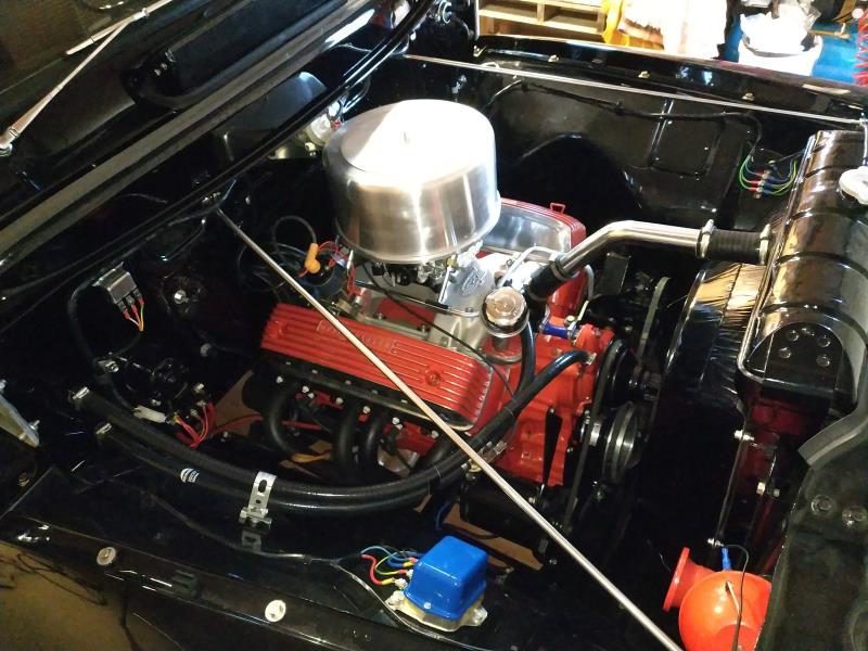 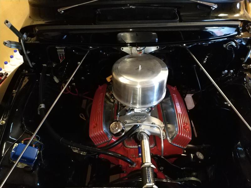 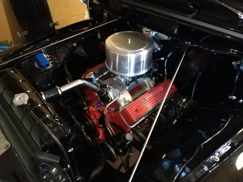
|
|
By Cliff - 6 Years Ago
|
|
NICE
|
|
By DryLakesRacer - 6 Years Ago
|
|
Cake lid air cleaner looks good on that Y
|
|
By miker - 6 Years Ago
|
|
Really nice detailing on the whole works. Good luck
|
|
By FORD DEARBORN - 6 Years Ago
|
Nice work and we're waiting for Friday, the best..................
|
|
By capelo - 6 Years Ago
|
|
thanks guys, tomorrow is the day, after the initial start-up what is the advance that you would recommend for the dealer?
|
|
By capelo - 6 Years Ago
|
first problem I have to modify the starter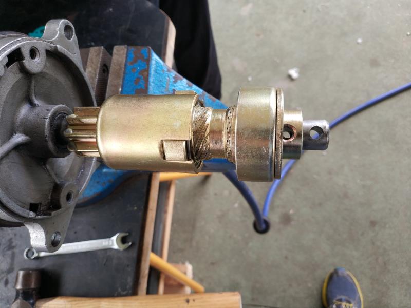
|
|
By Ted - 6 Years Ago
|
capelo (4/30/2020)
Thanks guys. Tomorrow is the day. After the initial start-up what is the advance that you would recommend for the distributor?
With the vacuum advance disconnected from the carburetor and the engine revved up so that all the mechanical advance is in (3000 rpm?), then set the ignition timing so it’s at 38° BTDC. If your damper does not have the 38° mark, you’ll need to put one there. When the engine comes back to idle, you’ll probably see 12-15° BTDC but that number can vary depending upon how the advance curve within the distributor is set up and the idle rpm. In a perfect world the ignition timing at idle with the vacuum advance either hooked up or disconnected is expected to be the same. This is assuming you are using the ported vacuum connection on the carburetor and not using vacuum from a direct source.
|
|
By capelo - 6 Years Ago
|
|
Thanks Ted for the comments. I solved the initial problem with the starter, but I think I have messed up, I was regulating the accelerator pedal stroke with the carb already loaded with gasoline, I have tried the start three times and it does not start, it turns but it only had small intention to start, I think too much gasoline came in, I'm going to wait a few hours and check everything again before trying again. I already started badly with this, if the best thing is that it rotates shortly before the start .... the thing is no longer going well. Ted as a fact I know not to have you now in my garage 😏
|
|
By Robs36Ford - 6 Years Ago
|
Leaving excess fuel in a closed cylinder could wash the rings dry.
I would remove the Spark Plugs, crank the engine for 3-5 seconds to clear excess fuel then blow the spark plugs dry with compressed air. Reinstall and try to start the engine. If timing and carb are setup good then it should fire right up.
|
|
By capelo - 6 Years Ago
|
|
Well the afternoon had been better, after a review the engine started, 20 minutes at 2200rpm without any problem oil pressure at 50 psi, there only seems to be a small oil leak in the area of the oil pump that when I cool down I will check. Then I have regulated the ignition without vacuum at 3000rpm 38 ° of advance and at idle 950rpm 17 ° of advance, when connecting the vacuum it continues at 17 °. I have a video but I don't know if it can be uploaded here
|
|
By capelo - 6 Years Ago
|
Robs36Ford (5/1/2020)
Leaving excess fuel in a closed cylinder could wash the rings dry. I would remove the Spark Plugs, crank the engine for 3-5 seconds to clear excess fuel then blow the spark plugs dry with compressed air. Reinstall and try to start the engine. If timing and carb are setup good then it should fire right up.
the problem was not the fuel, the distributor had poorly graduated, I was too late
|
|
By DryLakesRacer - 6 Years Ago
|
|
Response 368 and it runs.... There was a lot of rebuilding going on in this post..:<)
|
|
By Lord Gaga - 6 Years Ago
|
CONGRATULATIONS!
Here's hoping it runs as good as it looks. 
|
|
By capelo - 6 Years Ago
|
|
https://youtu.be/ghVVmELl5xw
|
|
By Cliff - 6 Years Ago
|
|
Nice, Good Job
|
|
By 57RancheroJim - 6 Years Ago
|
Well done, sounds great!
|
|
By FORD DEARBORN - 6 Years Ago
|
Very nice well done, everything............
|
|
By DryLakesRacer - 6 Years Ago
|
|
Great job..🍻🍻🍻🍻
|
|
By capelo - 6 Years Ago
|
|
thanks guys hope the end result is right
|
|
By capelo - 6 Years Ago
|
|
any advice on set-up and shooting will always be welcome
|
|
By Tedster - 6 Years Ago
|
capelo (5/3/2020)
any advice on set-up and shooting will always be welcome
"Don't Fire Till You See The Whites Of Their Eyes".
Wait, what? I think something is lost in the translation.
Anyhoo, great job! Sounds great.
Happy Motoring!
|
|
By capelo - 6 Years Ago
|
Tedster (5/3/2020)
capelo (5/3/2020)
any advice on set-up and shooting will always be welcome "Don't Fire Till You See The Whites Of Their Eyes". Wait, what? I think something is lost in the translation. Anyhoo, great job! Sounds great. Happy Motoring!
Thaks 👍🍻
|
|
By capelo - 6 Years Ago
|
|
Hello guys. I've already done my first 70 miles with no apparent problem. I would like to know if the carb is properly regulated but I don't know how to do it, what do I have to look at?
|
|
By Ted - 6 Years Ago
|
While a wide band oxygen sensor would be a nice tool to have to see what the actual fuel mixtures are, I realize that is a piece of equipment that’s not feasible for most hobbyists. Keep in mind that with only seventy miles on the engine, it’s still breaking in so don’t be making any wholesale changes until you get some more miles on the engine. If you hear any clatter, pinging and/or detonation, then double check the ignition timing. It may be necessary to unhook the vacuum advance to the distributor if 'pinging' is evident and examine exactly how much ignition advance is being thrown at the engine.
A vacuum gauge will permit you to get the best idle fuel mixture. Removing and reading the spark plugs after driving the vehicle for awhile will give you an idea of the overall fuel mixture. As long as the spark plug center porcelains are reasonably clean, your fuel mixture is in the ball park. If you check the spark plugs after a considerable amount of idle time, I would expect them to look to be on the rich side which would be misleading.
Assuming that the color change on the spark plug electrode strap is in the middle or the bottom edge of the bend, your ignition timing is okay. If the color change on the strap is closer to the centerline of the plug, then you need some additional ignition timing added. This may require shortening up the lead in the distributor so that the total timing is not altered. Likewise, if the color change on the spark plug electrode strap is closer to the outside edge of the spark plug, then you need to back the timing up some.
|
|
By capelo - 6 Years Ago
|
Ted (5/20/2020)
While a wide band oxygen sensor would be a nice tool to have to see what the actual fuel mixtures are, I realize that is a piece of equipment that’s not feasible for most hobbyists. Keep in mind that with only seventy miles on the engine, it’s still breaking in so don’t be making any wholesale changes until you get some more miles on the engine. If you hear any clatter, pinging and/or detonation, then double check the ignition timing. It may be necessary to unhook the vacuum advance to the distributor if 'pinging' is evident and examine exactly how much ignition advance is being thrown at the engine. A vacuum gauge will permit you to get the best idle fuel mixture. Removing and reading the spark plugs after driving the vehicle for awhile will give you an idea of the overall fuel mixture. As long as the spark plug center porcelains are reasonably clean, your fuel mixture is in the ball park. If you check the spark plugs after a considerable amount of idle time, I would expect them to look to be on the rich side which would be misleading. Assuming that the color change on the spark plug electrode strap is in the middle or the bottom edge of the bend, your ignition timing is okay. If the color change on the strap is closer to the centerline of the plug, then you need some additional ignition timing added. This may require shortening up the lead in the distributor so that the total timing is not altered. Likewise, if the color change on the spark plug electrode strap is closer to the outside edge of the spark plug, then you need to back the timing up some.
Thanks Ted.
I will wait to have more miles in my truck, at the moment I have only changed the height of the balls in the carburettor tanks. I have not seen detonation noises. On looking at the gap for a good mix, what values should it be in my case?
|
|
By Ted - 6 Years Ago
|
|
For carbureted engines with street rated compression ratios, 0.035” is the recommended gap for the spark plugs. Filing the electrodes back so that the ends are aligned with the centerline of the spark plugs tends to help.
|
|
By capelo - 6 Years Ago
|
|
And about the value with the vacuum gauge for carburettor regularization, what should be the measurement?
|
|
By capelo - 6 Years Ago
|
Ted (5/20/2020)
For carbureted engines with street rated compression ratios, 0.035” is the recommended gap for the spark plugs. Filing the electrodes back so that the ends are aligned with the centerline of the spark plugs tends to help.
thanks Ted. That I have already done so, I followed one of your articles for it.
|
|
By Ted - 6 Years Ago
|
capelo (5/20/2020)
And about the value with the vacuum gauge for carburettor regularization, what should be the measurement?
There's not a specific value you are aiming for as that's simply due to the fact that all engines are not the same when modifications are thrown into the mix. Here’s the simplified version for your Summit carburetor. With the vacuum gauge hooked up to a direct vacuum port (intake manifold or any port located below the carburetor throttle blades) and with the engine fully warmed up and at idle, back out both idle mixture screws for the highest vacuum reading. If you started with both mixture screws at 1½ turns open from the seated position, then work both screws in or out the same amounts. Once you have done this and obtained the highest manifold vacuum reading, then slowly screw in each idle mixture screw until the vacuum reading just starts to drop off and then just turn each screw ¼ turn out.
|
|
By capelo - 6 Years Ago
|
Ted (5/21/2020)
capelo (5/20/2020)
And about the value with the vacuum gauge for carburettor regularization, what should be the measurement? There's not a specific value you are aiming for as that's simply due to the fact that all engines are not the same when modifications are thrown into the mix. Here’s the simplified version for your Summit carburetor. With the vacuum gauge hooked up to a direct vacuum port (intake manifold or any port located below the carburetor throttle blades) and with the engine fully warmed up and at idle, back out both idle mixture screws for the highest vacuum reading. If you started with both mixture screws at 1½ turns open from the seated position, then work both screws in or out the same amounts. Once you have done this and obtained the highest manifold vacuum reading, then slowly screw in each idle mixture screw until the vacuum reading just starts to drop off and then just turn each screw ¼ turn out.
Alright thanks, the final quarter turn is to the right or left
|
|
By capelo - 6 Years Ago
|
is there a better option to connect the throttle?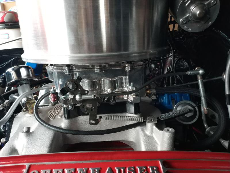
|
|
By Ted - 6 Years Ago
|
capelo (5/24/2020)
Is there a better option to connect the throttle? 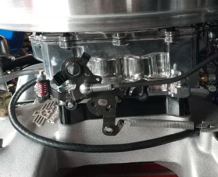
Raising the attachment point where the throttle linkage connects to the carburetor will have the throttle less sensitive or less twitchy when driving the vehicle. The vehicles are typically easier to drive with the throttle linkage attached higher versus being closer to the pivot point of the throttle shaft.
|
|
By Ted - 6 Years Ago
|
capelo (5/24/2020)
Ted (5/21/2020)
capelo (5/20/2020)
And about the value with the vacuum gauge for carburettor regularization, what should be the measurement? There's not a specific value you are aiming for as that's simply due to the fact that all engines are not the same when modifications are thrown into the mix. Here’s the simplified version for your Summit carburetor. With the vacuum gauge hooked up to a direct vacuum port (intake manifold or any port located below the carburetor throttle blades) and with the engine fully warmed up and at idle, back out both idle mixture screws for the highest vacuum reading. If you started with both mixture screws at 1½ turns open from the seated position, then work both screws in or out the same amounts. Once you have done this and obtained the highest manifold vacuum reading, then slowly screw in each idle mixture screw until the vacuum reading just starts to drop off and then just turn each screw ¼ turn out. Alright thanks, the final quarter turn is to the right or left
For the idle fuel screw adjustments, ‘out’ is CCW (counter clockwise) and ‘in’ is CW (clockwise). The idle mixture screws control the amount of fuel going into the engine at idle. Turning them CW reduces the fuel while turning them CCW increases the amount of fuel. That final ¼ turn adjustment (CCW) being ‘out’ is opening up the fuel flow some more thus increasing the fuel flow at idle.
|
|
By 1946international - 6 Years Ago
|
OK so now take it all back apart and do it again, so we will have something to read!
Joking aside, this has been a GREAT thread, Lots of info, thanks to all that contributed.
|
|
By DryLakesRacer - 6 Years Ago
|
|
I’ve never seen so many rebuild an engine. But this many reading I sure can understand it..
|
|
By capelo - 6 Years Ago
|
Ted (5/24/2020)
capelo (5/24/2020)
Is there a better option to connect the throttle? Raising the attachment point where the throttle linkage connects to the carburetor will have the throttle less sensitive or less twitchy when driving the vehicle. The vehicles are typically easier to drive with the throttle linkage attached higher versus being closer to the pivot point of the throttle shaft.
Hello greetings.
I have modified the hooked a hole higher and I have changed the spring for a slightly softer one, as you say it had no precision in the accelerator it was jumping, now it is much better👍
|
|
By capelo - 6 Years Ago
|
1946international (5/29/2020)
OK so now take it all back apart and do it again, so we will have something to read! Joking aside, this has been a GREAT thread, Lots of info, thanks to all that contributed.
thanks, now it's time to do miles👍
|
|
By capelo - 6 Years Ago
|
Ted (5/24/2020)
capelo (5/24/2020)
Ted (5/21/2020)
capelo (5/20/2020)
And about the value with the vacuum gauge for carburettor regularization, what should be the measurement? There's not a specific value you are aiming for as that's simply due to the fact that all engines are not the same when modifications are thrown into the mix. Here’s the simplified version for your Summit carburetor. With the vacuum gauge hooked up to a direct vacuum port (intake manifold or any port located below the carburetor throttle blades) and with the engine fully warmed up and at idle, back out both idle mixture screws for the highest vacuum reading. If you started with both mixture screws at 1½ turns open from the seated position, then work both screws in or out the same amounts. Once you have done this and obtained the highest manifold vacuum reading, then slowly screw in each idle mixture screw until the vacuum reading just starts to drop off and then just turn each screw ¼ turn out. Alright thanks, the final quarter turn is to the right or left For the idle fuel screw adjustments, ‘out’ is CCW (counter clockwise) and ‘in’ is CW (clockwise). The idle mixture screws control the amount of fuel going into the engine at idle. Turning them CW reduces the fuel while turning them CCW increases the amount of fuel. That final ¼ turn adjustment (CCW) being ‘out’ is opening up the fuel flow some more thus increasing the fuel flow at idle.
Thanks👍
|
|
By capelo - 6 Years Ago
|
DryLakesRacer (5/29/2020)
I’ve never seen so many rebuild an engine. But this many reading I sure can understand it..
Thanks 👍
|
|
By MoonShadow - 6 Years Ago
|
|
This is one of the things I love about this group. A rookie Y-Block builder asked weeks worth of basic questions and got advice, tips and suggestion to help complete his project. Now he's on the road and people are helping him work the bugs out. I love you guys!
|
|
By dennis22 - 6 Years Ago
|
MoonShadow (6/1/2020)
This is one of the things I love about this group. A rookie Y-Block builder asked weeks worth of basic questions and got advice, tips and suggestion to help complete his project. Now he's on the road and people are helping him work the bugs out. I love you guys!
I’ll second that!!! I too was a complete beginner a few years back and received great thoughtful advice with no judgment! I’m still a beginner, but now I know my way around a Yblock and managed a successful rebuild thanks to all you guys!
So thank you all too!
|
|
By FORD DEARBORN - 6 Years Ago
|
MoonShadow, my exact feelings. I couldn't have put it in better words. Just think if this forum and it's entire membership were able to run the U.S. ................
|
|
By capelo - 6 Years Ago
|
|
very good guys, thanks for the comments I have a question that I have to ask to lower the revolutions when starting cold and how I reduce the time it is accelerating, when I use it it is not so cold and when starting every time it is too much accelerating 1500rpm and so it seems to me too long
|
|
By Ted - 6 Years Ago
|
|
Are you using the electric choke? If so, then there is a screw located behind and under the choke coil for the hi-speed idle that can be adjusted to bring the cold start rpm speed down. Backing off the choke coil adjustment can help to speed up and/or reduce the amount of time that the choke is actually activated. The power source for the electric choke needs to be from a switched ‘ON’ connection and a constant 12 volt supply. Under no circumstances should the electric choke power supply be siphoned off of the power supply feeding the coil. Also insure that you have good ground on the engine that in some form connects to the battery.
|
|
By capelo - 6 Years Ago
|
Ted (6/5/2020)
Are you using the electric choke? If so, then there is a screw located behind and under the choke coil for the hi-speed idle that can be adjusted to bring the cold start rpm speed down. Backing off the choke coil adjustment can help to speed up and/or reduce the amount of time that the choke is actually activated. The power source for the electric choke needs to be from a switched ‘ON’ connection and a constant 12 volt supply. Under no circumstances should the electric choke power supply be siphoned off of the power supply feeding the coil. Also insure that you have good ground on the engine that in some form connects to the battery.
Yes, the choke is electric, in the image you can see the connection
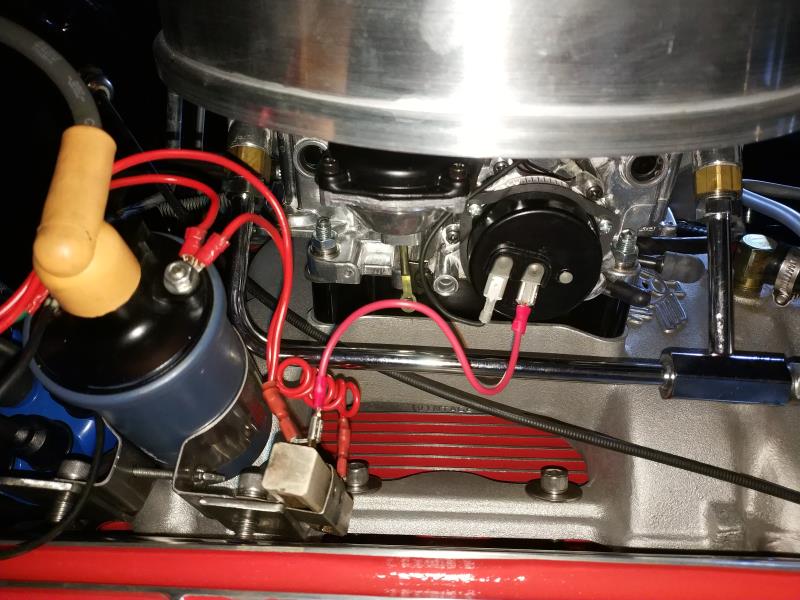
|
|
By oldcarmark - 6 Years Ago
|
|
Power for the Choke should be directly from Ignition Switch Accessory Terminal.. Should also have an inline Fuse to protect the Circuit.
|
|
By NY59F100 - 6 Years Ago
|
Capelo,
Is that a two-pronged voltage reducer? It looks like you have power run to one post on the reducer and power coming off the two prongs to power the coil and the electric choke. Like Ted and Oldcarmark said, the power must be direct from the ignition. Don’t split power off to power both the coil and the electric choke. Run separate wires.
|
|
By capelo - 6 Years Ago
|
NY59F100 (6/9/2020)
Capelo, Is that a two-pronged voltage reducer? It looks like you have power run to one post on the reducer and power coming off the two prongs to power the coil and the electric choke. Like Ted and Oldcarmark said, the power must be direct from the ignition. Don’t split power off to power both the coil and the electric choke. Run separate wires.
thanks guys for the tips so i will 👍
|
|
By capelo - 6 Years Ago
|
Hi guys 👋 I haven't written for a long time, I'm still running the engine, it has 1500 miles, I took out the spark plug 2 and 6, I took some photos, if someone can tell me to come, thank you.
spark plug 2
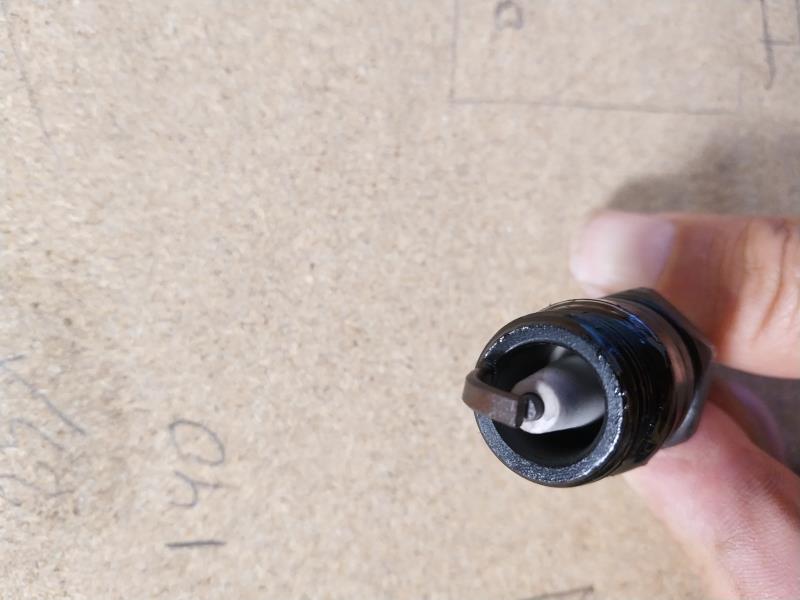 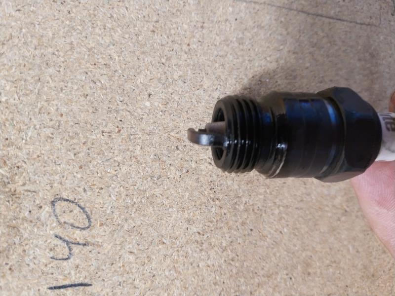 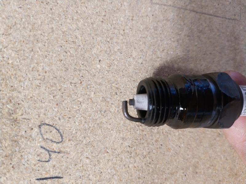
Spark plug 6
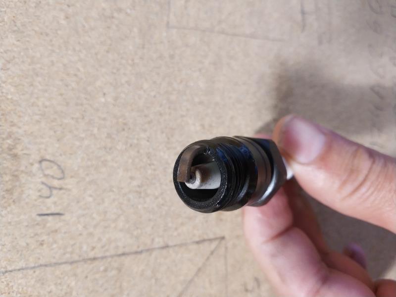 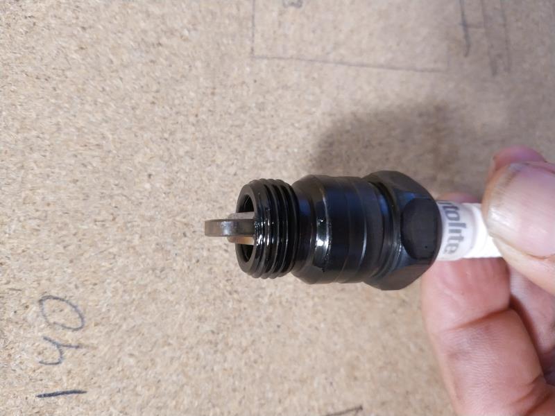 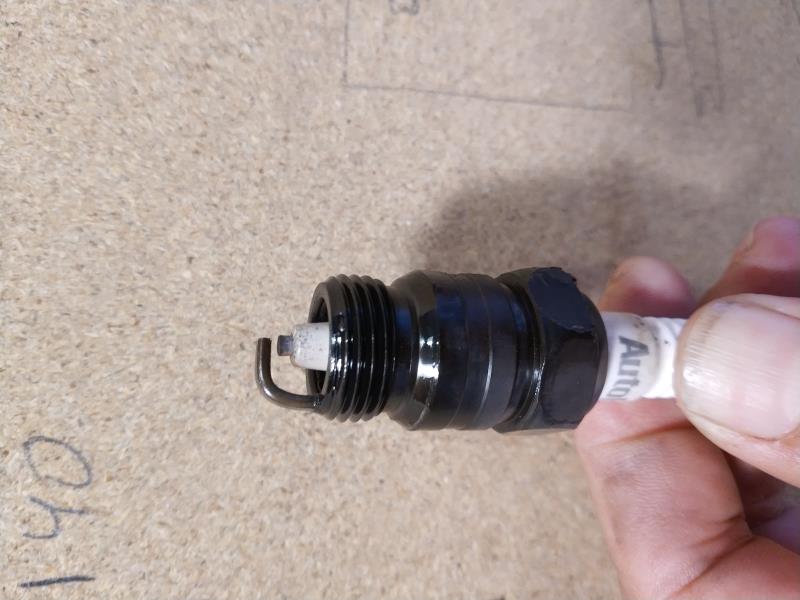
|
|
By Ted - 6 Years Ago
|
|
While those spark plugs appear to be burning cleanly, they still look like a lot of idle time and/or the engine is running on the cold side. Had the engine been at temperature just prior to removing the plugs for examination? What temperature thermostat are you running?
|
|
By capelo - 6 Years Ago
|
Ted (9/11/2020)
While those spark plugs appear to be burning cleanly, they still look like a lot of idle time and/or the engine is running on the cold side. Had the engine been at temperature just prior to removing the plugs for examination? What temperature thermostat are you running?
Thanks Ted, the engine had been stopped for five days, I have a thermostat but I'm not sure I know how much it is but I think it's 180f
|
|
By Ted - 6 Years Ago
|
It’s usually best to check spark plug coloring immediately after doing some road driving. A 180°F thermostat is the recommended heat range for most Y’s. A 160°F thermostat can be on the cool side and may not permit condensation that forms inside the engine to burn off adequately and especially if the engine is not ran for longer periods or used just for short hops.
Other than that, how does the engine run when you jump into the throttle?
|
|
By capelo - 6 Years Ago
|
Ted (9/12/2020)
It’s usually best to check spark plug coloring immediately after doing some road driving. A 180°F thermostat is the recommended heat range for most Y’s. A 160°F thermostat can be on the cool side and may not permit condensation that forms inside the engine to burn off adequately and especially if the engine is not ran for longer periods or used just for short hops. Other than that, how does the engine run when you jump into the throttle?
The truth is that it has been a very big change in terms of performance, I am very happy with the result, I only have a small oil leak that I have not yet located the origin. My outings are not usually very long, they are usually about 40 km on a regional road, with my three-speed manual gearbox, circular ground between 2000 and 3000 rpm, but when I pressed the accelerator you can feel the thrust and when it goes over 3000rpm it shows to a plus, the response is good in any range but from there there is a big difference, yesterday I pushed a little uphill and soon it got to 4000rpm and 80 miles per hour, it was in a tunnel and I love the sound when you contribute I only notice a problem in first gear and trying to go very slowly there I have to step on the clutch pedal. But at the moment very happy with the whole.
|