|
Group: Forum Members
Last Active: 3 Years Ago
Posts: 160,
Visits: 31.8K
|
Thanks for the tip, what I don't see is any shade of aluminum color. Unless you're not talking about POR.
|
|
Group: Forum Members
Last Active: 2 days ago
Posts: 502,
Visits: 21.7K
|
Just a suggestion, I have seen a couple of engines done with a 2k paint that looks good. The advantage is carby cleaner and most other solvents wont bother it.
|
|
Group: Forum Members
Last Active: 3 Years Ago
Posts: 160,
Visits: 31.8K
|
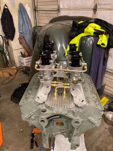
Just when you all thought I have given up or left the site, I'm still here. Been kinda lazy with this project but went out today and clear coated the engine turned parts, reblasted the other aluminum pieces and am on the hunt for the right aluminum paint for the intake runners. I'm looking at VHT SP106 flat silver right now but not sure if it has too much blue in it. I'm going to try Rustoleum Silver Caliper Paint tomorrow. After that and this heat wave we're going to have, it will back to the wrenches getting the intake/carb put together and running. Stay tuned.
|
|
Group: Forum Members
Last Active: 3 Years Ago
Posts: 160,
Visits: 31.8K
|
Before and after  
|
|
Group: Forum Members
Last Active: 3 Years Ago
Posts: 160,
Visits: 31.8K
|
|
|
Group: Forum Members
Last Active: 3 Years Ago
Posts: 160,
Visits: 31.8K
|
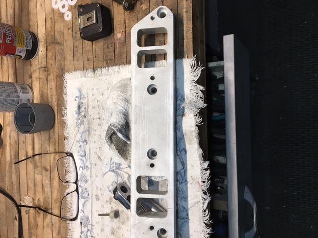
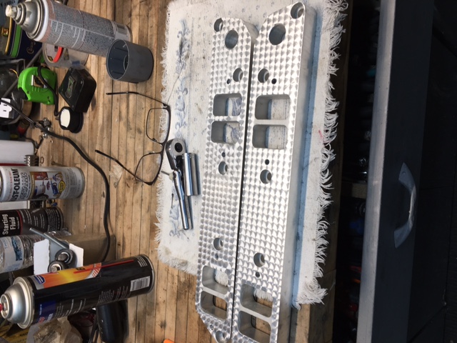
I just received the first picture of my Weber 368 project. I like the innovation  . Intake on the left is just welded (was 2 pieces) , on the right, sanded down
|
|
Group: Forum Members
Last Active: Last Year
Posts: 658,
Visits: 16.7K
|
Several people have jiggered the holes and removed the dowel pins on a FE bell housing to make it bolt up to a Lincoln Y..I never have, as you would have to spend a lot of effort centering the transmission with the crank.. For an automatic I used a Merc-o-matic bell to a 368 and modified it for a C4. For a stick I took a heavy truck bell and adapted that to a T-85 . A Scrub HD Saginaw 3 speed will adapt pretty easily to the truck bell.
|
|
Group: Administrators
Last Active: 2 days ago
Posts: 7.5K,
Visits: 205.9K
|
My understanding is that the LYB bell housing bolt pattern is on a slightly smaller bolt circle than what’s found on the FE. I’ve heard of people simply slotting the FE bell housing bolt holes inward and making them work on the LYB engines. ........But depending upon the dowel pins and how they are located in the different blocks, it may be difficult to get the transmission properly aligned with the crankshaft. I have no personal experience with this. Anyone with more information is welcome to chime in.
  Lorena, Texas (South of Waco) Lorena, Texas (South of Waco)
|
|
Group: Forum Members
Last Active: 3 Years Ago
Posts: 160,
Visits: 31.8K
|
are saying an FE adapter with fit a 368?
|
|
Group: Forum Members
Last Active: 10 hours ago
Posts: 380,
Visits: 4.8K
|
hi! do they make an adaptor for a FE? check with Royce but i believe it might work!
lincoln/merc. y-blocks &mel's bucyrus, ohio.
|