Profile Picture

Turn and High beam indicators

Posted By charliemccraney 15 Years Ago
You don't have permission to rate!
Author
Message
kcblueoval
Posted 15 Years Ago
View Quick Profile
Normally aspirated

Normally aspirated (34 reputation)Normally aspirated (34 reputation)Normally aspirated (34 reputation)Normally aspirated (34 reputation)Normally aspirated (34 reputation)Normally aspirated (34 reputation)Normally aspirated (34 reputation)Normally aspirated (34 reputation)Normally aspirated (34 reputation)

Group: Forum Members
Last Active: 10 Years Ago
Posts: 24, Visits: 252
Charlie you have really done a lot of work on this. You may need to go into production. I have a question about using a WHITE center block. I white block may (?) bleed light from one light well to another. A BLACK block may not bleed light from one light well to another. Before you glue this altogether you may want to test it. Let us know how it comes out. We are all curious to see the results. When & how do we place orders? Great job! You are a true Hot Rodder. Smile The new generation of old school R&D engineering. School of hard knocks.

Great Job!

kcblueoval
charliemccraney
Posted 15 Years Ago
View Quick Profile
Supercharged

Supercharged (9.8K reputation)Supercharged (9.8K reputation)Supercharged (9.8K reputation)Supercharged (9.8K reputation)Supercharged (9.8K reputation)Supercharged (9.8K reputation)Supercharged (9.8K reputation)Supercharged (9.8K reputation)Supercharged (9.8K reputation)

Group: Moderators
Last Active: 6 hours ago
Posts: 6.1K, Visits: 443.0K
The lights are 5mm but they come with thingies for mounting them in a panel which need a 1/4" hole.


Lawrenceville, GA
kcblueoval
Posted 15 Years Ago
View Quick Profile
Normally aspirated

Normally aspirated (34 reputation)Normally aspirated (34 reputation)Normally aspirated (34 reputation)Normally aspirated (34 reputation)Normally aspirated (34 reputation)Normally aspirated (34 reputation)Normally aspirated (34 reputation)Normally aspirated (34 reputation)Normally aspirated (34 reputation)

Group: Forum Members
Last Active: 10 Years Ago
Posts: 24, Visits: 252
what size hole did you need to drill for the lights?

Thanks,

kcblueoval
charliemccraney
Posted 15 Years Ago
View Quick Profile
Supercharged

Supercharged (9.8K reputation)Supercharged (9.8K reputation)Supercharged (9.8K reputation)Supercharged (9.8K reputation)Supercharged (9.8K reputation)Supercharged (9.8K reputation)Supercharged (9.8K reputation)Supercharged (9.8K reputation)Supercharged (9.8K reputation)

Group: Moderators
Last Active: 6 hours ago
Posts: 6.1K, Visits: 443.0K
GREENBIRD56 (8/18/2010)
Charlie - That is a really nice layout job - and a lot of think'um to boot - its going to be a pretty impressive in the finished state.


I've got an idea for some extra research/reading when you've got the time - look at some model railroading electronic project books. There are some "Radio Shack" voltage regulator chips and such - that will fix the brightness of your LED'sthrough a fairly wide range of input voltage - say 5 vdc to 15 vdc. By building a regulated power supply - you won't have the effect of "OHM's Law" working on your dropping resistor package.


Thanks! Each hole is sized for it's specific gauge. I even measured the bezels and laid it out so there is more or less a 1/4" gap between each gauge. Where possible, there is at least 1/4" between the bezel and the edge of the panel.


I'll look into a regulated power supply.


I added the wires to the indicator light board. They will match the colors of my Centech harness. So aside from adding the connector so I can plug it right into the harness, this part is done.


Lawrenceville, GA
GREENBIRD56
Posted 15 Years Ago
View Quick Profile
Supercharged

Supercharged (2.3K reputation)Supercharged (2.3K reputation)Supercharged (2.3K reputation)Supercharged (2.3K reputation)Supercharged (2.3K reputation)Supercharged (2.3K reputation)Supercharged (2.3K reputation)Supercharged (2.3K reputation)Supercharged (2.3K reputation)

Group: Forum Members
Last Active: Last Year
Posts: 1.7K, Visits: 102.7K
Charlie - That is a really nice layout job - and a lot of think'um to boot - its going to be a pretty impressive in the finished state.

I've got an idea for some extra research/reading when you've got the time - look at some model railroading electronic project books. There are some "Radio Shack" voltage regulator chips and such - that will fix the brightness of your LED's through a fairly wide range of input voltage - say 5 vdc to 15 vdc. By building a regulated power supply - you won't have the effect of "OHM's Law" working on your dropping resistor package. 

http://forums.y-blocksforever.com/uploads/images/9ea2bf28-00c4-4772-9ac7-d154.jpg 
 Steve Metzger       Tucson, Arizona

charliemccraney
Posted 15 Years Ago
View Quick Profile
Supercharged

Supercharged (9.8K reputation)Supercharged (9.8K reputation)Supercharged (9.8K reputation)Supercharged (9.8K reputation)Supercharged (9.8K reputation)Supercharged (9.8K reputation)Supercharged (9.8K reputation)Supercharged (9.8K reputation)Supercharged (9.8K reputation)

Group: Moderators
Last Active: 6 hours ago
Posts: 6.1K, Visits: 443.0K
I've made a little more progress over the last couple weekends.


All of the little patterns.


Now I have to finish the indicator light housing, lens, and preparing the stock panel for the new insert but I probably won't begin to complete this until the middle of September.


Lawrenceville, GA
YellowWing
Posted 15 Years Ago
View Quick Profile
Supercharged

Supercharged (296 reputation)Supercharged (296 reputation)Supercharged (296 reputation)Supercharged (296 reputation)Supercharged (296 reputation)Supercharged (296 reputation)Supercharged (296 reputation)Supercharged (296 reputation)Supercharged (296 reputation)

Group: Forum Members
Last Active: 12 Years Ago
Posts: 296, Visits: 1.8K
Charlie, that is an interesting project you have on your hands. Thanks for the update. Mike

1956 Fairlane Victoria (ORREO)


Overlooking Beautiful Rimrock AZ

charliemccraney
Posted 15 Years Ago
View Quick Profile
Supercharged

Supercharged (9.8K reputation)Supercharged (9.8K reputation)Supercharged (9.8K reputation)Supercharged (9.8K reputation)Supercharged (9.8K reputation)Supercharged (9.8K reputation)Supercharged (9.8K reputation)Supercharged (9.8K reputation)Supercharged (9.8K reputation)

Group: Moderators
Last Active: 6 hours ago
Posts: 6.1K, Visits: 443.0K
I made the circuit board today, my first ever. I found the math to determine the required resistance. The green leds need at least 612.5ohms for 14.4 volts so I used a 620ohm resistor for those. That's 60ohms less than I was testing with. I went with an 820ohm resistor for the blue light which is 140ohms greater than I was testing with. They all work after soldering so that's a good sign. Any required adjustments will be made after it's been installed and tested in the intended environment.

I just need to get some wire and add it to the board. When it's all done it will be plug and play.

I forgot to drill the mounting holes in the board but that's no big deal. I'll just have to be a little more careful when I do drill them.


This weekend, I started on a few pieces I'll need to finish the cluster.


Lawrenceville, GA
charliemccraney
Posted 15 Years Ago
View Quick Profile
Supercharged

Supercharged (9.8K reputation)Supercharged (9.8K reputation)Supercharged (9.8K reputation)Supercharged (9.8K reputation)Supercharged (9.8K reputation)Supercharged (9.8K reputation)Supercharged (9.8K reputation)Supercharged (9.8K reputation)Supercharged (9.8K reputation)

Group: Moderators
Last Active: 6 hours ago
Posts: 6.1K, Visits: 443.0K
Ah yes. Another night that I won't get to sleep early.


Here is my plan for the light panel.


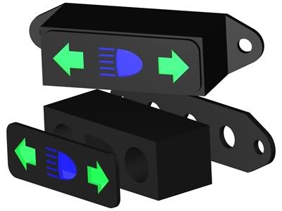
The block in the center will be a white plastic. I figure that will help make the lights as bright as possible.

I'm thinking that the back piece will be aluminum and there will be a thin gasket of some sort between that and the block. The LEDs have thingies so that they can be mounted to a panel and they will fit in the 3 larger holes of the aluminum part. And the two smaller holes are for fastening to the instrument panel. I'm also planning to support the circuit board with the same fasteners and some spacers just thick enough so that the board is supported but not under tension.

The front is going to be clear. I just gave them color to make the rendering a little more dramatic. The plan is to use printer labels to print my templates, figure out some way to stick them to some polycarbonate and have them lined up properly, paint it white, then peel of the stickers. This part will be glued carefully to the white part.


Lawrenceville, GA
charliemccraney
Posted 15 Years Ago
View Quick Profile
Supercharged

Supercharged (9.8K reputation)Supercharged (9.8K reputation)Supercharged (9.8K reputation)Supercharged (9.8K reputation)Supercharged (9.8K reputation)Supercharged (9.8K reputation)Supercharged (9.8K reputation)Supercharged (9.8K reputation)Supercharged (9.8K reputation)

Group: Moderators
Last Active: 6 hours ago
Posts: 6.1K, Visits: 443.0K
I'm sure my printer isn't designed for this paper. I think it is affecting the feed speed. If it goes through the printer slower than necessary it will shrink the drawing... I think. I used three pieces of paper so it looks like about .030" per page.


Lawrenceville, GA


Reading This Topic


Site Meter