Profile Picture

Turn and High beam indicators

Posted By charliemccraney 14 Years Ago
You don't have permission to rate!
Author
Message
charliemccraney
Posted 14 Years Ago
View Quick Profile
Supercharged

Supercharged (9.8K reputation)Supercharged (9.8K reputation)Supercharged (9.8K reputation)Supercharged (9.8K reputation)Supercharged (9.8K reputation)Supercharged (9.8K reputation)Supercharged (9.8K reputation)Supercharged (9.8K reputation)Supercharged (9.8K reputation)

Group: Moderators
Last Active: 2 hours ago
Posts: 6.1K, Visits: 437.4K
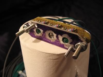
I made the circuit board today, my first ever. I found the math to determine the required resistance. The green leds need at least 612.5ohms for 14.4 volts so I used a 620ohm resistor for those. That's 60ohms less than I was testing with. I went with an 820ohm resistor for the blue light which is 140ohms greater than I was testing with. They all work after soldering so that's a good sign. Any required adjustments will be made after it's been installed and tested in the intended environment.

I just need to get some wire and add it to the board. When it's all done it will be plug and play.

I forgot to drill the mounting holes in the board but that's no big deal. I'll just have to be a little more careful when I do drill them.


This weekend, I started on a few pieces I'll need to finish the cluster.


Lawrenceville, GA
YellowWing
Posted 14 Years Ago
View Quick Profile
Supercharged

Supercharged (296 reputation)Supercharged (296 reputation)Supercharged (296 reputation)Supercharged (296 reputation)Supercharged (296 reputation)Supercharged (296 reputation)Supercharged (296 reputation)Supercharged (296 reputation)Supercharged (296 reputation)

Group: Forum Members
Last Active: 11 Years Ago
Posts: 296, Visits: 1.8K
Charlie, that is an interesting project you have on your hands. Thanks for the update. Mike

1956 Fairlane Victoria (ORREO)


Overlooking Beautiful Rimrock AZ

charliemccraney
Posted 14 Years Ago
View Quick Profile
Supercharged

Supercharged (9.8K reputation)Supercharged (9.8K reputation)Supercharged (9.8K reputation)Supercharged (9.8K reputation)Supercharged (9.8K reputation)Supercharged (9.8K reputation)Supercharged (9.8K reputation)Supercharged (9.8K reputation)Supercharged (9.8K reputation)

Group: Moderators
Last Active: 2 hours ago
Posts: 6.1K, Visits: 437.4K
I've made a little more progress over the last couple weekends.


All of the little patterns.


Now I have to finish the indicator light housing, lens, and preparing the stock panel for the new insert but I probably won't begin to complete this until the middle of September.


Lawrenceville, GA
GREENBIRD56
Posted 14 Years Ago
View Quick Profile
Supercharged

Supercharged (2.3K reputation)Supercharged (2.3K reputation)Supercharged (2.3K reputation)Supercharged (2.3K reputation)Supercharged (2.3K reputation)Supercharged (2.3K reputation)Supercharged (2.3K reputation)Supercharged (2.3K reputation)Supercharged (2.3K reputation)

Group: Forum Members
Last Active: Last Week
Posts: 1.7K, Visits: 102.7K
Charlie - That is a really nice layout job - and a lot of think'um to boot - its going to be a pretty impressive in the finished state.

I've got an idea for some extra research/reading when you've got the time - look at some model railroading electronic project books. There are some "Radio Shack" voltage regulator chips and such - that will fix the brightness of your LED's through a fairly wide range of input voltage - say 5 vdc to 15 vdc. By building a regulated power supply - you won't have the effect of "OHM's Law" working on your dropping resistor package. 

http://forums.y-blocksforever.com/uploads/images/9ea2bf28-00c4-4772-9ac7-d154.jpg 
 Steve Metzger       Tucson, Arizona

charliemccraney
Posted 14 Years Ago
View Quick Profile
Supercharged

Supercharged (9.8K reputation)Supercharged (9.8K reputation)Supercharged (9.8K reputation)Supercharged (9.8K reputation)Supercharged (9.8K reputation)Supercharged (9.8K reputation)Supercharged (9.8K reputation)Supercharged (9.8K reputation)Supercharged (9.8K reputation)

Group: Moderators
Last Active: 2 hours ago
Posts: 6.1K, Visits: 437.4K
GREENBIRD56 (8/18/2010)
Charlie - That is a really nice layout job - and a lot of think'um to boot - its going to be a pretty impressive in the finished state.


I've got an idea for some extra research/reading when you've got the time - look at some model railroading electronic project books. There are some "Radio Shack" voltage regulator chips and such - that will fix the brightness of your LED'sthrough a fairly wide range of input voltage - say 5 vdc to 15 vdc. By building a regulated power supply - you won't have the effect of "OHM's Law" working on your dropping resistor package.


Thanks! Each hole is sized for it's specific gauge. I even measured the bezels and laid it out so there is more or less a 1/4" gap between each gauge. Where possible, there is at least 1/4" between the bezel and the edge of the panel.


I'll look into a regulated power supply.


I added the wires to the indicator light board. They will match the colors of my Centech harness. So aside from adding the connector so I can plug it right into the harness, this part is done.


Lawrenceville, GA
kcblueoval
Posted 14 Years Ago
View Quick Profile
Normally aspirated

Normally aspirated (34 reputation)Normally aspirated (34 reputation)Normally aspirated (34 reputation)Normally aspirated (34 reputation)Normally aspirated (34 reputation)Normally aspirated (34 reputation)Normally aspirated (34 reputation)Normally aspirated (34 reputation)Normally aspirated (34 reputation)

Group: Forum Members
Last Active: 9 Years Ago
Posts: 24, Visits: 252
what size hole did you need to drill for the lights?

Thanks,

kcblueoval
charliemccraney
Posted 14 Years Ago
View Quick Profile
Supercharged

Supercharged (9.8K reputation)Supercharged (9.8K reputation)Supercharged (9.8K reputation)Supercharged (9.8K reputation)Supercharged (9.8K reputation)Supercharged (9.8K reputation)Supercharged (9.8K reputation)Supercharged (9.8K reputation)Supercharged (9.8K reputation)

Group: Moderators
Last Active: 2 hours ago
Posts: 6.1K, Visits: 437.4K
The lights are 5mm but they come with thingies for mounting them in a panel which need a 1/4" hole.


Lawrenceville, GA
kcblueoval
Posted 14 Years Ago
View Quick Profile
Normally aspirated

Normally aspirated (34 reputation)Normally aspirated (34 reputation)Normally aspirated (34 reputation)Normally aspirated (34 reputation)Normally aspirated (34 reputation)Normally aspirated (34 reputation)Normally aspirated (34 reputation)Normally aspirated (34 reputation)Normally aspirated (34 reputation)

Group: Forum Members
Last Active: 9 Years Ago
Posts: 24, Visits: 252
Charlie you have really done a lot of work on this. You may need to go into production. I have a question about using a WHITE center block. I white block may (?) bleed light from one light well to another. A BLACK block may not bleed light from one light well to another. Before you glue this altogether you may want to test it. Let us know how it comes out. We are all curious to see the results. When & how do we place orders? Great job! You are a true Hot Rodder. Smile The new generation of old school R&D engineering. School of hard knocks.

Great Job!

kcblueoval
charliemccraney
Posted 14 Years Ago
View Quick Profile
Supercharged

Supercharged (9.8K reputation)Supercharged (9.8K reputation)Supercharged (9.8K reputation)Supercharged (9.8K reputation)Supercharged (9.8K reputation)Supercharged (9.8K reputation)Supercharged (9.8K reputation)Supercharged (9.8K reputation)Supercharged (9.8K reputation)

Group: Moderators
Last Active: 2 hours ago
Posts: 6.1K, Visits: 437.4K
Thanks! I haven't been called a true hot rodder before. I really appreciate that.


I am a little concerned about light bleeding through. With the LEDs, most of the light is directed ahead of it rather than to the sides. As a result, the housing is not concerning me as much as the lens. The housing (white portion) will be Nylon. I already have it and it's nearly opaque. The cavities in the housing will be only as big as necessary and will approximate the shape of each symbol where reasonably possible. This will help to direct the light precisely where it needs to go.

I think the lens is going to be the trickiest part of this whole project. For the first version (hopefully the last), I have some adhesive backed pvc which I will stick to the back side of the lens with the appropriate shapes for the symbols cut out. On the front, I will mask off the symbols which will need to be placed almost exactly opposite the pvc symbols, and paint the lense white to match the instrument panel. The idea is that the pvc will allow only what light is needed to enter the lens, reducing the amount it bleeds and making for sharper looking symbols. ...We'll see if that happens.


I have since modified the housing design from the original. I think this one will make it a little easier to work with for R&D purposes. I'm not planning to do much gluing until I verify that it works.
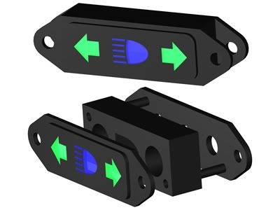


Here it is roughly fitted to the light support dealamajig. I don't want to install it yet. The led panel fitting thingies look like they will be a real pain to remove once installed. The metal piece is the part in the back in the rendered drawing.


Let me get it made before I think of any kind of production. It's a lot of work.


Lawrenceville, GA
charliemccraney
Posted 13 Years Ago
View Quick Profile
Supercharged

Supercharged (9.8K reputation)Supercharged (9.8K reputation)Supercharged (9.8K reputation)Supercharged (9.8K reputation)Supercharged (9.8K reputation)Supercharged (9.8K reputation)Supercharged (9.8K reputation)Supercharged (9.8K reputation)Supercharged (9.8K reputation)

Group: Moderators
Last Active: 2 hours ago
Posts: 6.1K, Visits: 437.4K
Wow, it was August when I last posted about this. I admit, I got lazy at the end of last year. With temperatures rising again, I've come out of hibernation. I pretty well finished the filler panel for the lower section of the instrument panel today. All that's left is to weld it in place.


This is the first time I've ever made something like this. I'm quite happy with the results.


I have made more progress on the indicator lights but not enough to post anything about just yet. That is pretty well all that is left to complete this project. Otherwise, I just gotta try not to warp everything when I weld it together.


Lawrenceville, GA


Reading This Topic


Site Meter