Profile Picture

Turn and High beam indicators

Posted By charliemccraney 14 Years Ago
You don't have permission to rate!
Author
Message
charliemccraney
Posted 10 Years Ago
View Quick Profile
Supercharged

Supercharged (9.8K reputation)Supercharged (9.8K reputation)Supercharged (9.8K reputation)Supercharged (9.8K reputation)Supercharged (9.8K reputation)Supercharged (9.8K reputation)Supercharged (9.8K reputation)Supercharged (9.8K reputation)Supercharged (9.8K reputation)

Group: Moderators
Last Active: 17 minutes ago
Posts: 6.1K, Visits: 437.3K
Alright, back to this project.

The housing LED housing and related components.  To cut out the approximate shapes you see in the 3rd picture, I used a template to mark holes to be drilled, 3/16" or bigger.  Then I used a dremel with a 1/8" carbide bur to cut out the shape, trying to stay tangent to all of the holes.


Since I had changed my design, it now meant that I had to locate the position for the new design.  Fortunately I had already marked the panel but had not cut out the hole for the original lens.  So I made a line through the center of the original markings and made a template for the new cutout which uses that line and an arc with the diameter of the instrument hole to get it lined up.  From there I drilled my holes and used a cutoff wheel to cut that portion out.


The panel is slightly curved in that area and with the clamping pressure of the speedo/tach bracket, I was not confident that it would stay in place.  So, I added a stud at the very bottom of the large center hole.  Welding tip - steel will not stick to copper and copper is a great heat sink.  I used some copper because the area where I was welding the stud was so small along with my stud fixture tool outlined earlier in the thread.  It offered extra support to the steel and prevented me from burning through the edges of the panel.  Where did I get the copper?  In the plumbing section of the hardware store.  I hammered it flat, gently as possible, then sanded it lightly.


Pretty much finished.  A little filler and sanding, and paint remains.


I added the wires to the LEDs.  I decided on Red/Green/Blue LEDs.  Because they are RGB I went with red, green, and blue wires for the anodes (+) and black for the cathode (-). That will make them easy to identify for future plans. It is automotive TXL wire.  I'm probably going to add something for strain relief so that the weight of the wires and vibration don't cause the LEDs to fail too soon.  The voltage regulators for the turn and high beam indicators are on the far left of the panel in the 2nd picture. It will be rubber mounted to reduce vibration.  I just need to add wiring to it. I'll wait until I have my wiring connectors here.


And, the magic!  With just one light lit, it does bleed through the lens a little but it is not bad at all.  It's not bad enough that I'm going to do anything about it.


Up next is to add wires to the regulator, some sort of strain relief for the LEDs, make the harness for the instrument panel, and then paint it.


Lawrenceville, GA
charliemccraney
Posted 12 Years Ago
View Quick Profile
Supercharged

Supercharged (9.8K reputation)Supercharged (9.8K reputation)Supercharged (9.8K reputation)Supercharged (9.8K reputation)Supercharged (9.8K reputation)Supercharged (9.8K reputation)Supercharged (9.8K reputation)Supercharged (9.8K reputation)Supercharged (9.8K reputation)

Group: Moderators
Last Active: 17 minutes ago
Posts: 6.1K, Visits: 437.3K
I made my test adjustable voltage regulator today. I bought some more hardware to simplify the job, a breadboard. It allows circuits to be set up without soldering.


It was a success.
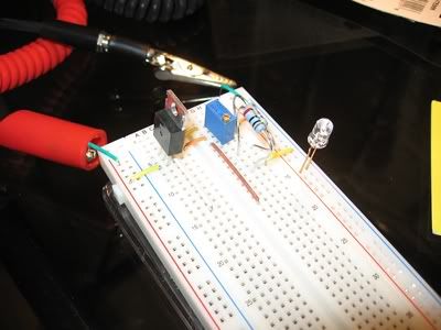


It works, I swear:


For more info: http://www.rodandcustommagazine.com/techarticles/1105rc_how_to_build_reliable_powerful_and_inexpensive_voltage_drops_part_ii_transistors/viewall.html


They provide a formula for figuring things out, V = 1.25(1 + (R2 / R1)).


I rearranged it for other stuff. Say you know your target output voltage, V and you've picked out a resistor, R1 and you need to know the resistance required for R2:

R2 = R1(V / 1.25 -1)


And if you know R2 and need R1:

R1 = R2 / (V / 1.25 -1)


This was useful because in my case, R2 is 14.7ohm (R2 is actually 2 resistors, a 10 and 4.7 ohm because the store was out of 15 ohm) and I was able to determine where to set the trimmer, 0 - 500ohm, to avoid damaging the LED with too high a voltage, though the max output voltage as configured is about 5.10volts.


I will probably make two versions of the board, the first with trimmers, that's the blue component with the screw on top. It is an adjustable resistor. Based on what I understand with the specs, it won't be a good idea to use it permanently, but it will allow me to get the brightness dialed in. Once I am satisfied with that, I can measure the resistance and build a board with the appropriate resistor. I'll build a second board rather than simply replacing the trimmers with resistors because I'm sure that adjustability will come in handy for dialing in future projects. The lights and regulator board will be separate components so replacement will be easy.


I didn't really like the green of the old LEDs so I picked a new green but it was super bright so I was worried that it would be too bright. "Warning! Do not stare at LED may injure eyes" is on the packaging. I like the color and I'm happy to see that it has quite a range for the voltage. It's rated at 3.2 volts but there is a faint glow at even 1.4 volts so it won't be too bright. Now that I know which components will be used, I can complete the design of the housing to suit the new symbols and layout.


Lawrenceville, GA
charliemccraney
Posted 12 Years Ago
View Quick Profile
Supercharged

Supercharged (9.8K reputation)Supercharged (9.8K reputation)Supercharged (9.8K reputation)Supercharged (9.8K reputation)Supercharged (9.8K reputation)Supercharged (9.8K reputation)Supercharged (9.8K reputation)Supercharged (9.8K reputation)Supercharged (9.8K reputation)

Group: Moderators
Last Active: 17 minutes ago
Posts: 6.1K, Visits: 437.3K
Alright, going a different direction.


Now I have to redesign the housing and circuit board and such but this new route will be much easier, even though I had everything made for the otherHehe I'm going to incorporate a voltage regulator as Steve suggested earlier in the thread - now's a good time to do it.


Lawrenceville, GA
charliemccraney
Posted 12 Years Ago
View Quick Profile
Supercharged

Supercharged (9.8K reputation)Supercharged (9.8K reputation)Supercharged (9.8K reputation)Supercharged (9.8K reputation)Supercharged (9.8K reputation)Supercharged (9.8K reputation)Supercharged (9.8K reputation)Supercharged (9.8K reputation)Supercharged (9.8K reputation)

Group: Moderators
Last Active: 17 minutes ago
Posts: 6.1K, Visits: 437.3K
Got started on the lens.


The lens "frosted" on the back side with 220 grit.


The light blocking film for the back side, made with adhesive backed pvc. This was made by sticking one of the printed labels seen in a picture above onto the pvc and cutting with an xacto knife. The tape over it allowed me to place it precisely.


The front masked for painting. This was applied with tape, in a similar fashion to the film above.


Hopefully the masks peel off without issue tomorrow. When I was doing my R&D I peeled them off after about 10 minutes. However, I now realize that I cannot just grab it immediately and peel them off. Shoulda thought of that. Oh well. It'll be another problem to solve if it doesn't work.


Success! I nicked it in one spot but managed to touch it up with a bit of paint on tip of a pin.


Lawrenceville, GA
pegleg
Posted 12 Years Ago
View Quick Profile
Supercharged

Supercharged (4.3K reputation)Supercharged (4.3K reputation)Supercharged (4.3K reputation)Supercharged (4.3K reputation)Supercharged (4.3K reputation)Supercharged (4.3K reputation)Supercharged (4.3K reputation)Supercharged (4.3K reputation)Supercharged (4.3K reputation)

Group: Forum Members
Last Active: 2 Years Ago
Posts: 3.0K, Visits: 8.7K
Very nice work Charlie, I'm jealous!

Frank/Rebop

Bristol, In ( by Elkhart) 


charliemccraney
Posted 12 Years Ago
View Quick Profile
Supercharged

Supercharged (9.8K reputation)Supercharged (9.8K reputation)Supercharged (9.8K reputation)Supercharged (9.8K reputation)Supercharged (9.8K reputation)Supercharged (9.8K reputation)Supercharged (9.8K reputation)Supercharged (9.8K reputation)Supercharged (9.8K reputation)

Group: Moderators
Last Active: 17 minutes ago
Posts: 6.1K, Visits: 437.3K
Today I was able to drill the holes in the panel and weld the studs onto the insert.


I had to make a tool to hold the studs while they were welded. This is what I cam up with using some scrap. Only as much pressure as is necessary is used with the clamps. It'll bend very easily while welding.


And this is where I'm at.


I'll use some filler to make it look like one piece. This will allow a clean look and make it relatively easy to make upgrades in the future.


Lawrenceville, GA
charliemccraney
Posted 12 Years Ago
View Quick Profile
Supercharged

Supercharged (9.8K reputation)Supercharged (9.8K reputation)Supercharged (9.8K reputation)Supercharged (9.8K reputation)Supercharged (9.8K reputation)Supercharged (9.8K reputation)Supercharged (9.8K reputation)Supercharged (9.8K reputation)Supercharged (9.8K reputation)

Group: Moderators
Last Active: 17 minutes ago
Posts: 6.1K, Visits: 437.3K
Some more progress.


Ground the welds.


Marked the original panel for the cutout.


Fitted the new insert.


Lawrenceville, GA
charliemccraney
Posted 12 Years Ago
View Quick Profile
Supercharged

Supercharged (9.8K reputation)Supercharged (9.8K reputation)Supercharged (9.8K reputation)Supercharged (9.8K reputation)Supercharged (9.8K reputation)Supercharged (9.8K reputation)Supercharged (9.8K reputation)Supercharged (9.8K reputation)Supercharged (9.8K reputation)

Group: Moderators
Last Active: 17 minutes ago
Posts: 6.1K, Visits: 437.3K
I had ordered a Haneline unit which has the indicator lights built in. It has all of the gauges of the two big units in one, slightly larger unit. I liked the looks of it a lot. But it was backordered for about 4 months. That made me uncomfortable about it. What if it breaks, how long will I have to wait for repair or replacement? So I cancelled it.


I took another look at Dakota digital later last night, and they do offer analog looking digital gauges. Too bad they didn't have them a year and a half ago - I did try to find some.


Lawrenceville, GA
The Master Cylinder
Posted 12 Years Ago
View Quick Profile
Supercharged

Supercharged (1.6K reputation)Supercharged (1.6K reputation)Supercharged (1.6K reputation)Supercharged (1.6K reputation)Supercharged (1.6K reputation)Supercharged (1.6K reputation)Supercharged (1.6K reputation)Supercharged (1.6K reputation)Supercharged (1.6K reputation)

Group: Forum Members
Last Active: 3 Years Ago
Posts: 974, Visits: 6.2K
charliemccraney (1/20/2012)
I don't like digital. I think they look cheesy. Plus I have too much invested to change direction now.


I agree, I don't like digital either, especially in an older vehicle. I have seen a aftermarket analog speedo with turn/high beam indicators that look pretty nice.

http://www.y-blocksforever.com/forums/Uploads/Images/af13a279-385d-4926-92f2-349a.jpg"The Master Cylinder"

Enjoying life at the beach in SOCAL Smooooth

charliemccraney
Posted 12 Years Ago
View Quick Profile
Supercharged

Supercharged (9.8K reputation)Supercharged (9.8K reputation)Supercharged (9.8K reputation)Supercharged (9.8K reputation)Supercharged (9.8K reputation)Supercharged (9.8K reputation)Supercharged (9.8K reputation)Supercharged (9.8K reputation)Supercharged (9.8K reputation)

Group: Moderators
Last Active: 17 minutes ago
Posts: 6.1K, Visits: 437.3K
I don't like digital. I think they look cheesy. Plus I have too much invested to change direction now.


Lawrenceville, GA


Reading This Topic


Site Meter