|
By YellowWing - 16 Years Ago
|
|
Charlie, is this what you are looking for? Hope it helps. Mike http://www.denniskirk.com/jsp/product_catalog/Product.jsp?skuId=407358&utm_source=google&utm_medium=cse http://www.denniskirk.com/jsp/product_catalog/Product.jsp?skuId=407359&utm_source=google&utm_medium=cse
|
|
By Bob's 55 - 16 Years Ago
|
But those are for left hand turns, do they also have ones for right hand turns?
|
|
By YellowWing - 16 Years Ago
|
|
Bob, they are for NASCAR drivers, don't need no right turns! Mike
|
|
By Bob's 55 - 16 Years Ago
|
|
Mike, thank you so much for clearing that up... so Charlie has a Nascar truck. But what's the High beam indicator for?
|
|
By YellowWing - 16 Years Ago
|
To indicate when you want to pass, very polite 
|
|
By rick55 - 16 Years Ago
|
Funny things these Nascars - they even have a light for when they are chasing someone.
$7.95 Drag Specialties Red Pursuit Snap-In Indicator Light
Dennis Kirk Part #: 407357
So you have a high beam indicator to let them know you are passing and another to let you know you are passing. It all sounds too confusing.
You would be in a spot of bother if you forgot to turn it off once you had made the pass.
All joking aside they are highly detailed bits of kit.
Regards
|
|
By YellowWing - 16 Years Ago
|
|
Charlie, are they the same size as the original lights? If not, what diameter and length are they? Thanks, Mike
|
|
By YellowWing - 16 Years Ago
|
That's OK, I found some nice LED's with chrome bezels I think ill use. They don't have symbols but with color and location I think even I car remember the meaning of each  Her e is the web address, sorry using Mozilla this morning so I can't post links. Mike Her e is the web address, sorry using Mozilla this morning so I can't post links. Mikewww.watsons-streetworks.com/lighting_equipment.html Done with IE. Would not work with Mozilla
|
|
By YellowWing - 16 Years Ago
|
Charlie, post above was edited with Mozilla and you can see what happens. Can't post photos either. This post is done on IE using the same proceedure. Strange  Mike Mikehttp://www.watsons-streetworks.com/lighting_equipment.html
|
|
By gritsngumbo - 16 Years Ago
|
|
Good information. I can use those. They look great! Charlie thanks for asking and Mike thanks for answering.
|
|
By YellowWing - 16 Years Ago
|
|
Charlie, post photos when you figure it out. I'm getting ready to redo my panel and am always looking for ideas. Mike
|
|
By John Mummert - 16 Years Ago
|
|
Charley, LED's are made to operate on 4-5 VDC so a dropping resistor is required. They are also polarity sensitive. Its been so long since I worked with any I don't remember the exact voltage or what polarity the identifed terminal is.
|
|
By bird55 - 16 Years Ago
|
|
Looks nice Charlie, I like the asymmetry.
|
|
By John Mummert - 16 Years Ago
|
|
Lookin good Charley!. Have you found what causes the heavy paper to shrink? Heat from the printer? You might be able to dim the blue one with a higher value resistor. But eventually you will reach a threshold voltage where it probably won't light at all. I know you can run them at less than design voltage. It will increase life and run cooler but I don't know how much it will dim. Sounds like an interesting project.
|
|
By YellowWing - 16 Years Ago
|
|
Charlie, that is an interesting project you have on your hands. Thanks for the update. Mike
|
|
By GREENBIRD56 - 16 Years Ago
|
|
Charlie - That is a really nice layout job - and a lot of think'um to boot - its going to be a pretty impressive in the finished state. I've got an idea for some extra research/reading when you've got the time - look at some model railroading electronic project books. There are some "Radio Shack" voltage regulator chips and such - that will fix the brightness of your LED's through a fairly wide range of input voltage - say 5 vdc to 15 vdc. By building a regulated power supply - you won't have the effect of "OHM's Law" working on your dropping resistor package.
|
|
By kcblueoval - 16 Years Ago
|
what size hole did you need to drill for the lights?
Thanks,
kcblueoval
|
|
By kcblueoval - 16 Years Ago
|
Charlie you have really done a lot of work on this. You may need to go into production. I have a question about using a WHITE center block. I white block may (?) bleed light from one light well to another. A BLACK block may not bleed light from one light well to another. Before you glue this altogether you may want to test it. Let us know how it comes out. We are all curious to see the results. When & how do we place orders? Great job! You are a true Hot Rodder.  The new generation of old school R&D engineering. School of hard knocks. The new generation of old school R&D engineering. School of hard knocks.
Great Job!
kcblueoval
|
|
By GREENBIRD56 - 15 Years Ago
|
|
Charlie - I think the article you found is in the May "Rod and Custom"???? It has all of the right stuff in there. I can scan you a copy if you want it? The regulator I built for my kids' caboose ran on DC volts - and worked like a charm - the running light LEDS never changed brightness at all so long as the volts on the track stayed above the min (for the LED's)
|
|
By Hutz 292 - 14 Years Ago
|
|
I haven't read every post but check Dakota Digital. I bought a gauge set for my 62 F100. They fit right into my factory spot. Comes with all the senders and you use the factory fuel sender. dakotadigital.com Their stuff is amazing. Give them a try.
|
|
By The Master Cylinder - 14 Years Ago
|
|
charliemccraney (1/20/2012)
I don't like digital. I think they look cheesy. Plus I have too much invested to change direction now.
I agree, I don't like digital either, especially in an older vehicle. I have seen a aftermarket analog speedo with turn/high beam indicators that look pretty nice.
|
|
By pegleg - 14 Years Ago
|
|
Very nice work Charlie, I'm jealous!
|
|
By charliemccraney - 16 Years Ago
|
Does anyone know of aftermarket indicators with arrows and the headlight icon.
I don't really like the leds and round lights many people use.
There's a panel on my Firebird with those 3 lights that will be perfect but they are a part of the instrument cluster and cannot be removed without at least minor damage to the cluster. I have yet to find a bad cluster and I can't bring myself to destroy a good one. So for that matter, even production pieces will be considered. I really only need lenses. The rest will be easy to make.
|
|
By charliemccraney - 16 Years Ago
|
Yes! Exactly like that! They're drag specialties so I can order them through work! Thanks!
I've looked through the catalog many times. I don't know how I missed them.
|
|
By Hoosier Hurricane - 16 Years Ago
|
|
On TV they talk about Nascar teams having different cars for different tracks. Now I understand. They need one with both LH and RH turn signals when they run on a road course.
|
|
By charliemccraney - 16 Years Ago
|
|
Got them today! Now I should have everything I need to finish with the layout of my instrument panel!
|
|
By charliemccraney - 16 Years Ago
|
They are not the same size as the lights in my truck. I opened one of them and I'm not satisfied with the quality. The paint is pealing off of the bezel. I looked at the other two through the packaging and they look the same. 3 out of 3 bad = crappy product.
I'll get the dimensions if you're still interested, but they're not going on my truck. Back to the drawing board. I'm going to try to figure out how I can make my own lenses.
|
|
By charliemccraney - 16 Years Ago
|
I saw those at the top of that page about a week ago. I called, hoping they had the symbols but they don't.
Posting links shouldn't have to do with Mozilla. It's what I'm using.
http://www.watsons-streetworks.com/lighting_equipment.html
|
|
By charliemccraney - 16 Years Ago
|
I think I know what's happening. You're clicking the url button, pasting the address, and clicking ok.
First paste the link in the body of the text, http://www.watsons-streetworks.com/lighting_equipment.html, highlight it, then click the url button and paste the url. You can highlight any text and it will work, for instance,
Watsosns Streetworks, done with Mozilla.
|
|
By charliemccraney - 16 Years Ago
|
|
Alright, my goal will be to integrate the indicator lights into the gauge panel so that they are invisible until illuminated. I have an idea how to do this. I'll try to do some experimentation this weekend. It'll essentially be the same sort of technique used to make hidden taillights, and marker lights on hotrods. It'll be neat if I pull it off.
|
|
By charliemccraney - 16 Years Ago
|
I don't think I'm going to do the invisible look. There are several problems. First, the light bleeds as it passes through the clear and painted lens so it does not produce as sharp an image as I would like. Second, I'm painting the cluster white and it results in the colors becoming more like pastels and that's not manly. Third, I don't have the patience to color sand the cluster to get the uniform look I want; without this, imperfections in the thickness of the paint show up when the light is illuminated.
I'm going to order the materials I need this week and do a little more experimenting but I'll probably end up doing a light panel which will be painted white with a clear lens and then the colored lenses behind it which should blend in well. The execution of this one will actually be a bit trickier but it's the kind of tricky I have patience for.
|
|
By charliemccraney - 16 Years Ago
|
I have the design of the gauge panel pretty well finished. The circles around the perimeter mark where either bolts or welded studs will fasten this panel into a cut out original panel. I'll probably do studs because that will allow me to use filler and make it look like one piece.
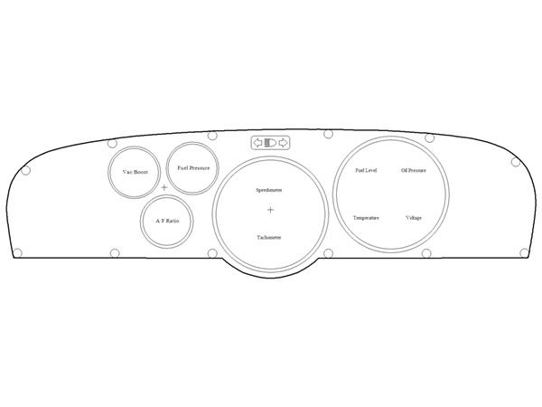
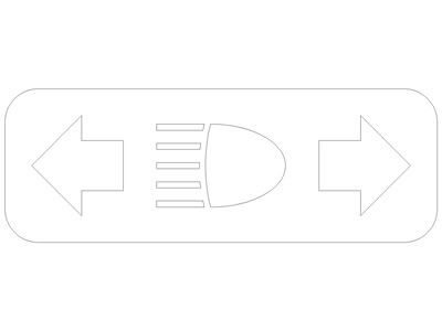
A larger view of the indicator light concept.
I picked up some LED's from fry's to play with. Apparently there's more to them as one blew almost immediately and the other was getting hot. Anyhow, they are available in several different colors which will simplify things. With a clear lens, the color is quite rich. This will eliminate the need for colored lenses and I think a clear lens will look better against a white background.
|
|
By charliemccraney - 16 Years Ago
|
|
That's exactly what it is. The instructions on the packaging weren't clear to me but a visit to the manufacturer's website cleared it up.
|
|
By charliemccraney - 16 Years Ago
|
I am very pleased with the layout. I normally like symmetry but 3 big ol gauges would have been too much. And there's room to spare! I do wish I could have had all of the gauges be the same brand and series.
Ford really ruined any chance of symmetry without major work. The gauge panel is sorta tapered. I think it's about 1/4" difference from one side to the other.
I just finished printing my test template on some scrap paper. Now I'm going to print it on the heavy stuff which will be used to transfer to steel.
|
|
By charliemccraney - 16 Years Ago
|
And the template is finished.
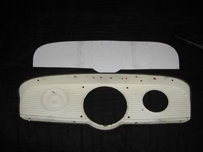 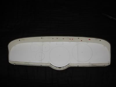
The heavier paper shrinks the drawing slightly along the X axis for some reason. I'll have to take note of that for future templates and keep it in mind when I'm cutting this piece out. I verified it against my test print out and my final draft of the instrument panel outline.
Edit: It was about .090" off which will throw my clearances way out of whack. So I scaled X by 1.004 and now it looks right.
|
|
By charliemccraney - 16 Years Ago
|
I got new LEDs and appropriate resistors. The blue one is a nice shade of blue but it might end up being too bright. The shade of the green one is not quite what I want and it might be dimmer than I need for the daytime. They are different, maybe different series; the blue one is clear but when illuminated is blue. The green one is green when not illuminated. I'm also doing my preliminary testing with a 9v battery so they'll probably be brighter when used as intended. Comparing the brightness of these on paper is not as straight forward as comparing bulbs. With a bulb you just look at the wattage. With LEDs you consider the intensity and beam angle. So a more intense but smaller angle LED can be as bright as a less intense, larger angle LED. Welcome to the world of electronics, I guess.
So tomorrow, I'll swing by Fry's to see if there is a different green and a dimmer blue. If not I'll work with those I have and deal with it later.
Now I need to adjust my drawing according to the pitch of the prototyping board so that the LEDs are centered with their respective symbols. ...That will most likely mean I have to print another template.
|
|
By charliemccraney - 16 Years Ago
|
|
I'm sure my printer isn't designed for this paper. I think it is affecting the feed speed. If it goes through the printer slower than necessary it will shrink the drawing... I think. I used three pieces of paper so it looks like about .030" per page.
|
|
By charliemccraney - 16 Years Ago
|
Ah yes. Another night that I won't get to sleep early.
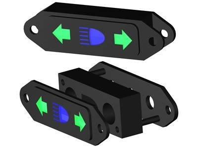
Here is my plan for the light panel.
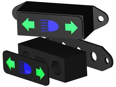
The block in the center will be a white plastic. I figure that will help make the lights as bright as possible.
I'm thinking that the back piece will be aluminum and there will be a thin gasket of some sort between that and the block. The LEDs have thingies so that they can be mounted to a panel and they will fit in the 3 larger holes of the aluminum part. And the two smaller holes are for fastening to the instrument panel. I'm also planning to support the circuit board with the same fasteners and some spacers just thick enough so that the board is supported but not under tension.
The front is going to be clear. I just gave them color to make the rendering a little more dramatic. The plan is to use printer labels to print my templates, figure out some way to stick them to some polycarbonate and have them lined up properly, paint it white, then peel of the stickers. This part will be glued carefully to the white part.
|
|
By charliemccraney - 16 Years Ago
|
I made the circuit board today, my first ever. I found the math to determine the required resistance. The green leds need at least 612.5ohms for 14.4 volts so I used a 620ohm resistor for those. That's 60ohms less than I was testing with. I went with an 820ohm resistor for the blue light which is 140ohms greater than I was testing with. They all work after soldering so that's a good sign. Any required adjustments will be made after it's been installed and tested in the intended environment.
I just need to get some wire and add it to the board. When it's all done it will be plug and play.
I forgot to drill the mounting holes in the board but that's no big deal. I'll just have to be a little more careful when I do drill them.
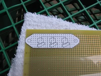 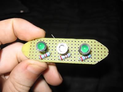
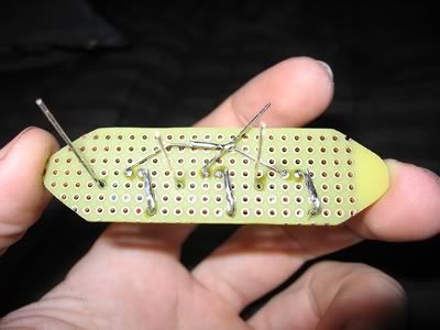
This weekend, I started on a few pieces I'll need to finish the cluster.
 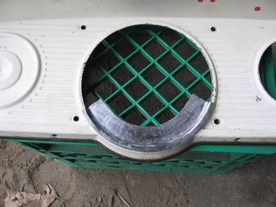
|
|
By charliemccraney - 16 Years Ago
|
I've made a little more progress over the last couple weekends.
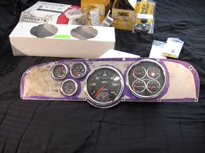
All of the little patterns.
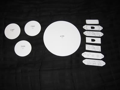
Now I have to finish the indicator light housing, lens, and preparing the stock panel for the new insert but I probably won't begin to complete this until the middle of September.
|
|
By charliemccraney - 16 Years Ago
|
|
GREENBIRD56 (8/18/2010)
Charlie - That is a really nice layout job - and a lot of think'um to boot - its going to be a pretty impressive in the finished state.
I've got an idea for some extra research/reading when you've got the time - look at some model railroading electronic project books. There are some "Radio Shack" voltage regulator chips and such - that will fix the brightness of your LED'sthrough a fairly wide range of input voltage - say 5 vdc to 15 vdc. By building a regulated power supply - you won't have the effect of "OHM's Law" working on your dropping resistor package.
Thanks! Each hole is sized for it's specific gauge. I even measured the bezels and laid it out so there is more or less a 1/4" gap between each gauge. Where possible, there is at least 1/4" between the bezel and the edge of the panel.
I'll look into a regulated power supply.
I added the wires to the indicator light board. They will match the colors of my Centech harness. So aside from adding the connector so I can plug it right into the harness, this part is done.
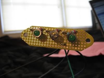 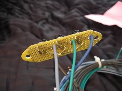
|
|
By charliemccraney - 16 Years Ago
|
|
The lights are 5mm but they come with thingies for mounting them in a panel which need a 1/4" hole.
|
|
By charliemccraney - 16 Years Ago
|
Thanks! I haven't been called a true hot rodder before. I really appreciate that.
I am a little concerned about light bleeding through. With the LEDs, most of the light is directed ahead of it rather than to the sides. As a result, the housing is not concerning me as much as the lens. The housing (white portion) will be Nylon. I already have it and it's nearly opaque. The cavities in the housing will be only as big as necessary and will approximate the shape of each symbol where reasonably possible. This will help to direct the light precisely where it needs to go.
I think the lens is going to be the trickiest part of this whole project. For the first version (hopefully the last), I have some adhesive backed pvc which I will stick to the back side of the lens with the appropriate shapes for the symbols cut out. On the front, I will mask off the symbols which will need to be placed almost exactly opposite the pvc symbols, and paint the lense white to match the instrument panel. The idea is that the pvc will allow only what light is needed to enter the lens, reducing the amount it bleeds and making for sharper looking symbols. ...We'll see if that happens.
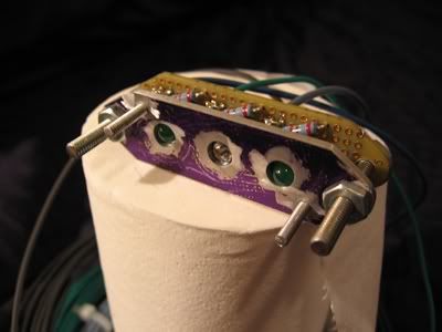
I have since modified the housing design from the original. I think this one will make it a little easier to work with for R&D purposes. I'm not planning to do much gluing until I verify that it works.
Here it is roughly fitted to the light support dealamajig. I don't want to install it yet. The led panel fitting thingies look like they will be a real pain to remove once installed. The metal piece is the part in the back in the rendered drawing.
Let me get it made before I think of any kind of production. It's a lot of work.
|
|
By charliemccraney - 15 Years Ago
|
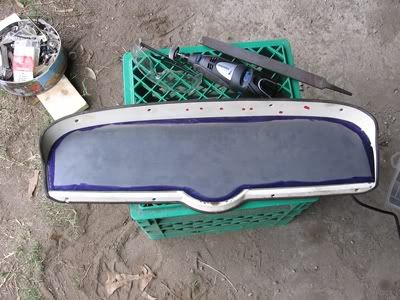
Wow, it was August when I last posted about this. I admit, I got lazy at the end of last year. With temperatures rising again, I've come out of hibernation. I pretty well finished the filler panel for the lower section of the instrument panel today. All that's left is to weld it in place.
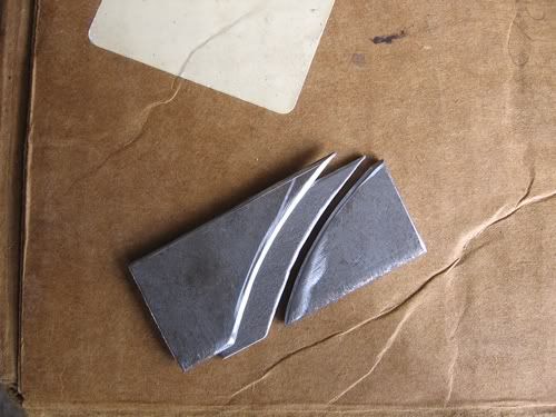 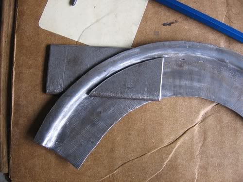
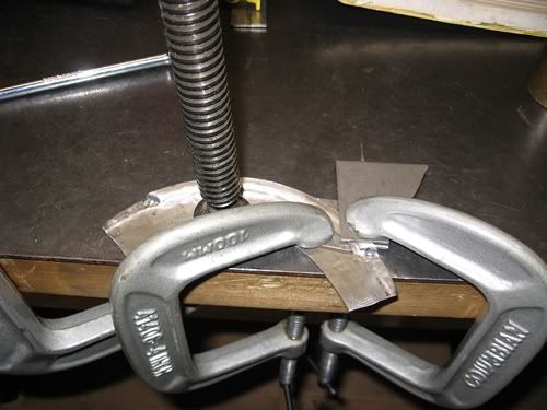 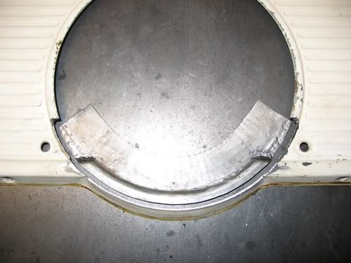
This is the first time I've ever made something like this. I'm quite happy with the results.
I have made more progress on the indicator lights but not enough to post anything about just yet. That is pretty well all that is left to complete this project. Otherwise, I just gotta try not to warp everything when I weld it together.
|
|
By charliemccraney - 15 Years Ago
|
Today I completed the light housing. I started with a chunk of nylon, cut away what wasn't a light housing, and voila a light housing.
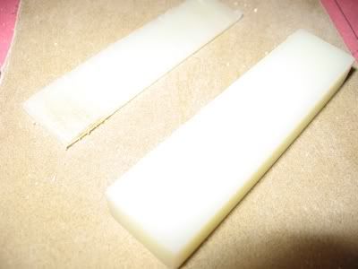
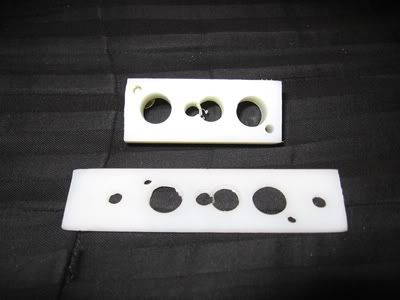 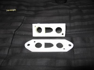
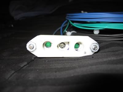 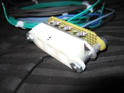
All that remains is the lens. If anything, now it's guaranteed that I'll have functional lights. I'm still not 100% sure how I'll pull off the lens.
|
|
By charliemccraney - 15 Years Ago
|
I have figured out how to make the lens.
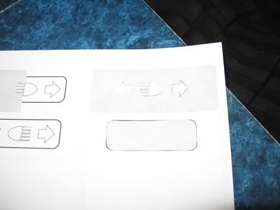
I will cut all of the shapes from labels which I will print with my computer. I will then transfer all of those shapes to the polycarbonate with the help of some scotch tape to simplify the alignment. This way I can mask the areas I do not want to paint. The scotch tape worked out a lot better than I thought it would. I just stick the shapes on well, and try to press down only on the shapes. carefully peel the tape off and it does pull the top layer of the shapes off but leaves a bottom layer which is still enough to keep paint off. Other than cutting it out of the polycarbonate sheet, what you see is exactly how the it will be made. The bigger sticker, on the back will be a thin film of pcv, this is to help ensure that the light goes through the lens only where I want it to go. I am going to make another test lens and the only change will be that I will sand the back side to give it a frosted appearance. I thought it would be neat to leave it clear but I don't like it. I can see the LED's and it just looks unfinished that way. So it needs a little fine tuning but at least I pretty well know how to do it. It looks a lot better in person than that last picture indicates.
 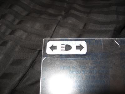
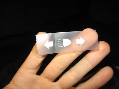 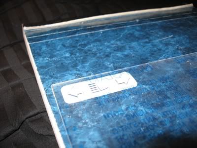
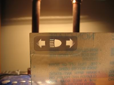 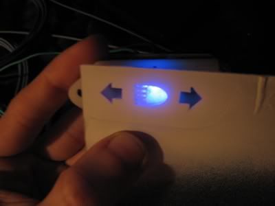
Alright, I couldn't resist. I carefully peeled the sticker away on the back, sanded it with 220 and put the sticker back. That is the answer. The frosted appearance will also make it blend better with the panel which will be white. So, experimentation done, time to make the real thing.
|
|
By charliemccraney - 15 Years Ago
|
|
GREENBIRD56 (8/18/2010)
I've got an idea for some extra research/reading when you've got the time - look at some model railroading electronic project books. There are some "Radio Shack" voltage regulator chips and such - that will fix the brightness of your LED'sthrough a fairly wide range of input voltage - say 5 vdc to 15 vdc. By building a regulated power supply - you won't have the effect of "OHM's Law" working on your dropping resistor package.
I haven't done much research on this subject. A couple weeks ago, I picked up a magazine which had an article about building voltage regulators. One is a transistorized variable regulator, variable meaning it can be built to provide any output within a certain range, not that you can adjust it with a knob or something like that. The article wasn't clear about input voltage but I have a feeling it's exactly what you're talking about, Steve. So if I have any issues, once it's up and running, I'll build one. A stable output voltage, regardless of input might come in handy.
|
|
By charliemccraney - 15 Years Ago
|
|
I think that's it. It starts with one type of regulator that is not variable, then goes into the variable regulators, and finally adding complimentary transistors and a trick about adding a diode increase the output for certain situations. There are 5 or 6 circuit diagrams.
|
|
By charliemccraney - 15 Years Ago
|
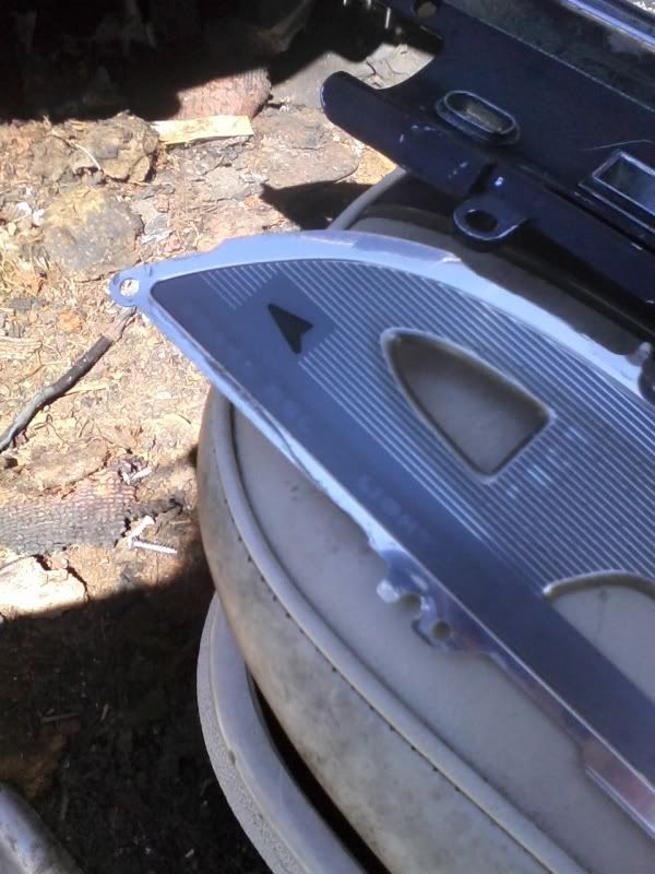
No more progress, yet, but while I was at the salvage yard last weekend I saw one way the factory did it. Just a hole punched in a panel, some translucent plastic and tape!
 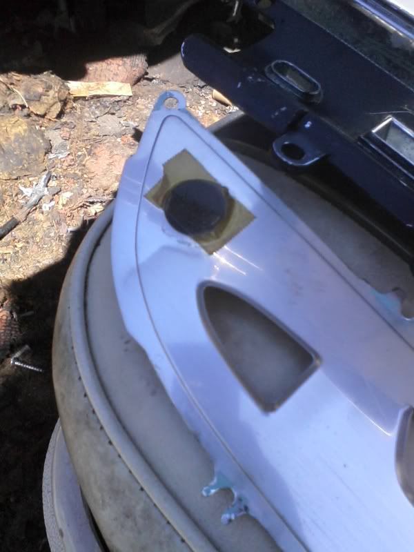
|
|
By charliemccraney - 14 Years Ago
|
Woohoo! Finally, time to get more done with this! I aim to be done with this by summer.
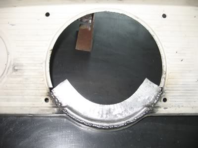 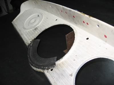
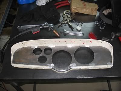
Getting it lined up tor the first tack was tricky. A combination of the panel not being flat, and my novice metal working skills. The solution I came up with is to use magnets to hold it in place and a bolt so that I could use the threads for fine adjustment. The mass of the bolt was not significant enough to stay in place with the force of the piece acting on it so the exhaust clamp prevented the bolt from moving.
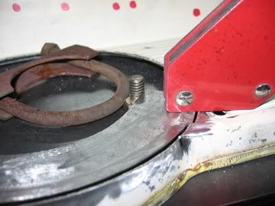
Now I need to grind the welds smooth, cut out the center of the panel and drill mounting holes for the new insert, weld the mounting studs to the insert, paint it and make the lens for the indicator lights. The hard work is done!
|
|
By charliemccraney - 14 Years Ago
|
|
I don't like digital. I think they look cheesy. Plus I have too much invested to change direction now.
|
|
By charliemccraney - 14 Years Ago
|
I had ordered a Haneline unit which has the indicator lights built in. It has all of the gauges of the two big units in one, slightly larger unit. I liked the looks of it a lot. But it was backordered for about 4 months. That made me uncomfortable about it. What if it breaks, how long will I have to wait for repair or replacement? So I cancelled it.
I took another look at Dakota digital later last night, and they do offer analog looking digital gauges. Too bad they didn't have them a year and a half ago - I did try to find some.
|
|
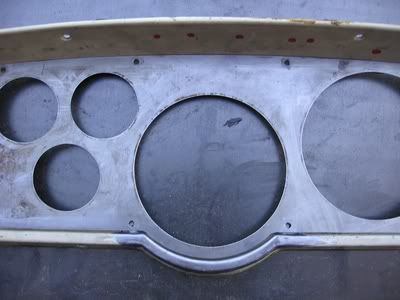
By charliemccraney - 14 Years Ago
|
Some more progress.
Ground the welds.
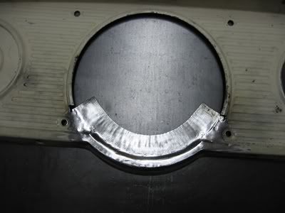 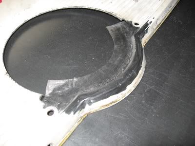
Marked the original panel for the cutout.
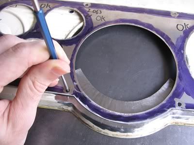 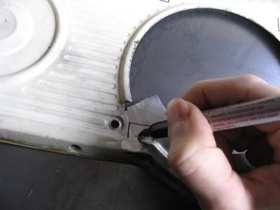
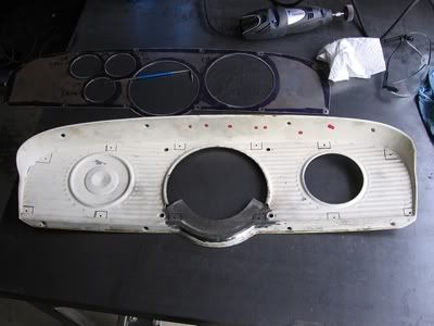 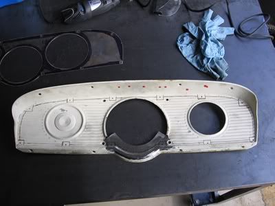
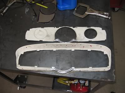
Fitted the new insert.
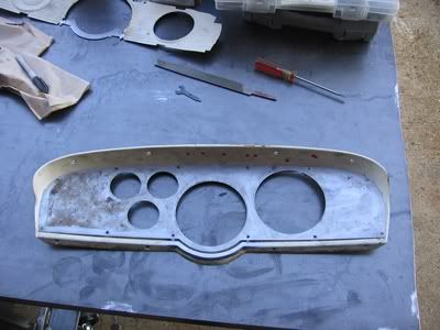 
|
|
By charliemccraney - 14 Years Ago
|
Today I was able to drill the holes in the panel and weld the studs onto the insert.
I had to make a tool to hold the studs while they were welded. This is what I cam up with using some scrap. Only as much pressure as is necessary is used with the clamps. It'll bend very easily while welding.
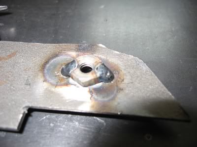 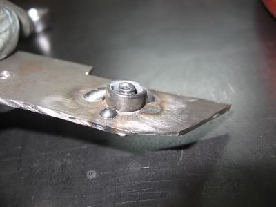
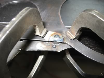 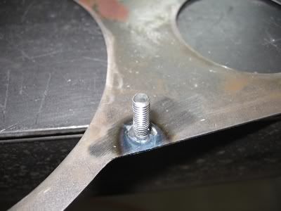
And this is where I'm at.
 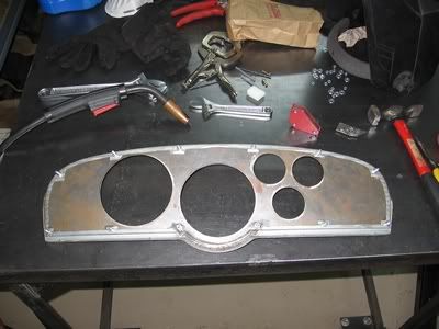
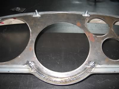
I'll use some filler to make it look like one piece. This will allow a clean look and make it relatively easy to make upgrades in the future.
|
|
By charliemccraney - 14 Years Ago
|
Got started on the lens.
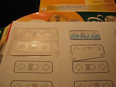 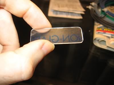
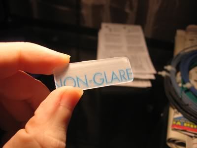
The lens "frosted" on the back side with 220 grit.
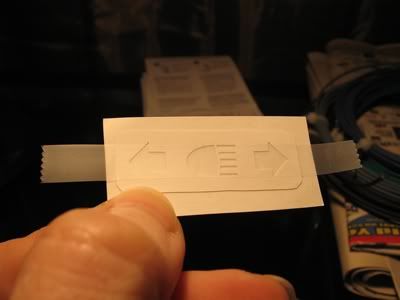
The light blocking film for the back side, made with adhesive backed pvc. This was made by sticking one of the printed labels seen in a picture above onto the pvc and cutting with an xacto knife. The tape over it allowed me to place it precisely.
 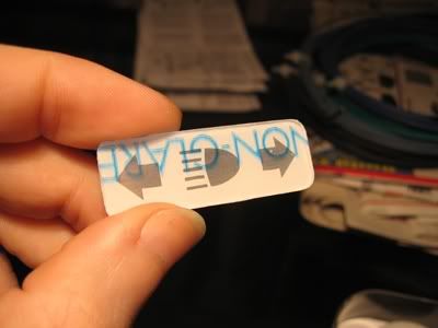
The front masked for painting. This was applied with tape, in a similar fashion to the film above.
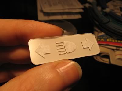 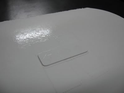
Hopefully the masks peel off without issue tomorrow. When I was doing my R&D I peeled them off after about 10 minutes. However, I now realize that I cannot just grab it immediately and peel them off. Shoulda thought of that. Oh well. It'll be another problem to solve if it doesn't work.
Success! I nicked it in one spot but managed to touch it up with a bit of paint on tip of a pin.
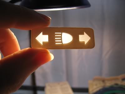
|
|
By charliemccraney - 14 Years Ago
|
Alright, going a different direction.
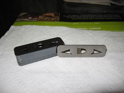 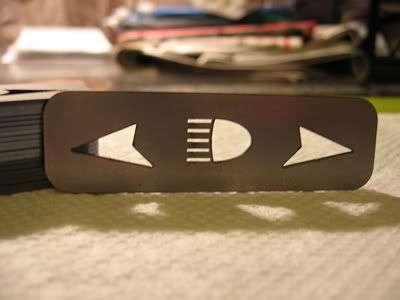
Now I have to redesign the housing and circuit board and such but this new route will be much easier, even though I had everything made for the other I'm going to incorporate a voltage regulator as Steve suggested earlier in the thread - now's a good time to do it. I'm going to incorporate a voltage regulator as Steve suggested earlier in the thread - now's a good time to do it.
|
|
By charliemccraney - 14 Years Ago
|
I made my test adjustable voltage regulator today. I bought some more hardware to simplify the job, a breadboard. It allows circuits to be set up without soldering.
It was a success.
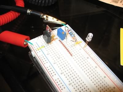
It works, I swear:
For more info: http://www.rodandcustommagazine.com/techarticles/1105rc_how_to_build_reliable_powerful_and_inexpensive_voltage_drops_part_ii_transistors/viewall.html
They provide a formula for figuring things out, V = 1.25(1 + (R2 / R1)).
I rearranged it for other stuff. Say you know your target output voltage, V and you've picked out a resistor, R1 and you need to know the resistance required for R2:
R2 = R1(V / 1.25 -1)
And if you know R2 and need R1:
R1 = R2 / (V / 1.25 -1)
This was useful because in my case, R2 is 14.7ohm (R2 is actually 2 resistors, a 10 and 4.7 ohm because the store was out of 15 ohm) and I was able to determine where to set the trimmer, 0 - 500ohm, to avoid damaging the LED with too high a voltage, though the max output voltage as configured is about 5.10volts.
I will probably make two versions of the board, the first with trimmers, that's the blue component with the screw on top. It is an adjustable resistor. Based on what I understand with the specs, it won't be a good idea to use it permanently, but it will allow me to get the brightness dialed in. Once I am satisfied with that, I can measure the resistance and build a board with the appropriate resistor. I'll build a second board rather than simply replacing the trimmers with resistors because I'm sure that adjustability will come in handy for dialing in future projects. The lights and regulator board will be separate components so replacement will be easy.
I didn't really like the green of the old LEDs so I picked a new green but it was super bright so I was worried that it would be too bright. "Warning! Do not stare at LED may injure eyes" is on the packaging. I like the color and I'm happy to see that it has quite a range for the voltage. It's rated at 3.2 volts but there is a faint glow at even 1.4 volts so it won't be too bright. Now that I know which components will be used, I can complete the design of the housing to suit the new symbols and layout.
|
|
By charliemccraney - 12 Years Ago
|
|
Alright, back to this project.
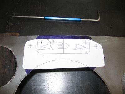
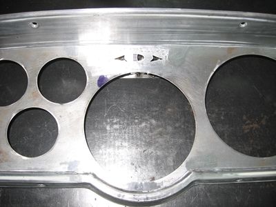
The housing LED housing and related components. To cut out the approximate shapes you see in the 3rd picture, I used a template to mark holes to be drilled, 3/16" or bigger. Then I used a dremel with a 1/8" carbide bur to cut out the shape, trying to stay tangent to all of the holes.
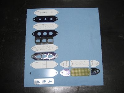 
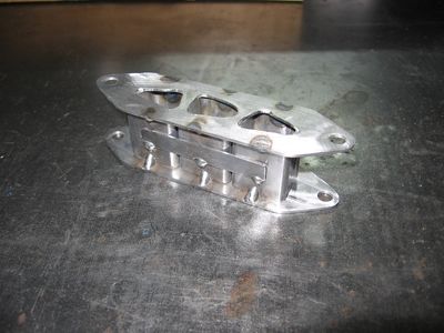
Since I had changed my design, it now meant that I had to locate the position for the new design. Fortunately I had already marked the panel but had not cut out the hole for the original lens. So I made a line through the center of the original markings and made a template for the new cutout which uses that line and an arc with the diameter of the instrument hole to get it lined up. From there I drilled my holes and used a cutoff wheel to cut that portion out.
 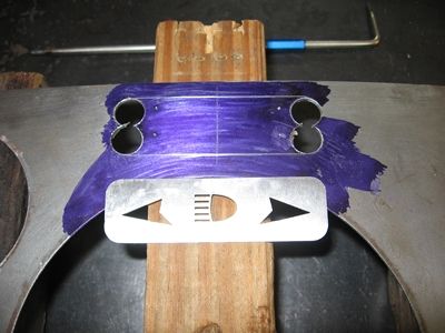
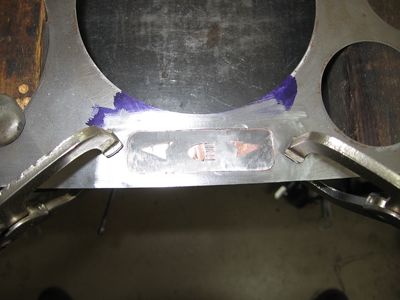
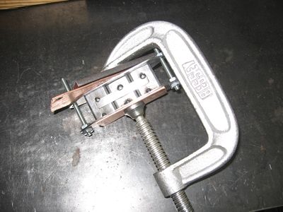
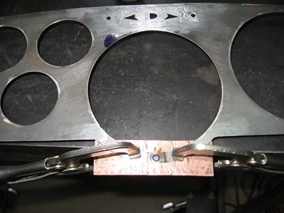
The panel is slightly curved in that area and with the clamping pressure of the speedo/tach bracket, I was not confident that it would stay in place. So, I added a stud at the very bottom of the large center hole. Welding tip - steel will not stick to copper and copper is a great heat sink. I used some copper because the area where I was welding the stud was so small along with my stud fixture tool outlined earlier in the thread. It offered extra support to the steel and prevented me from burning through the edges of the panel. Where did I get the copper? In the plumbing section of the hardware store. I hammered it flat, gently as possible, then sanded it lightly.
 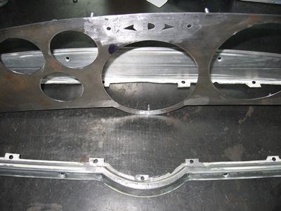
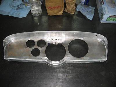
Pretty much finished. A little filler and sanding, and paint remains.
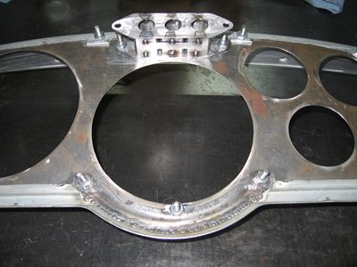 
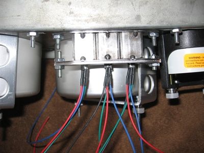
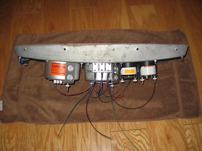
I added the wires to the LEDs. I decided on Red/Green/Blue LEDs. Because they are RGB I went with red, green, and blue wires for the anodes (+) and black for the cathode (-). That will make them easy to identify for future plans. It is automotive TXL wire. I'm probably going to add something for strain relief so that the weight of the wires and vibration don't cause the LEDs to fail too soon. The voltage regulators for the turn and high beam indicators are on the far left of the panel in the 2nd picture. It will be rubber mounted to reduce vibration. I just need to add wiring to it. I'll wait until I have my wiring connectors here.
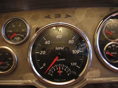
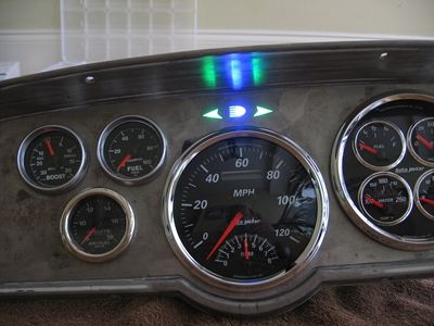
And, the magic! With just one light lit, it does bleed through the lens a little but it is not bad at all. It's not bad enough that I'm going to do anything about it.
 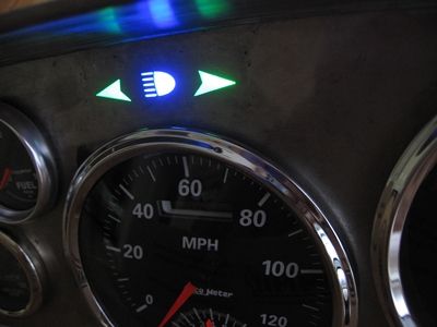
Up next is to add wires to the regulator, some sort of strain relief for the LEDs, make the harness for the instrument panel, and then paint it. |