|
Author
|
Message
|
|
KULTULZ
|
|
|
Group: Forum Members
Last Active: Last Month
Posts: 1.8K,
Visits: 306.4K
|
Thanks for the information regarding the MEL engine. Brings back memories when I did some modifications to a 383 and installed it in a 62 Galaxie in the 60's but that would be a story for a new thread.
I for one would be very interested in that info ... 
____________________________
|
|
|
|
|
Ted
|
|
|
Group: Administrators
Last Active: Yesterday
Posts: 7.5K,
Visits: 205.9K
|
Hoosier Hurricane (7/21/2025)
Ted, was it you or someone else that drilled a small hole into the oil feed passage to the front cam bearing that dribbled oil (or maybe even a small stream) to the front face of the block above the crank gear to spill oil onto the timing gears? I remember reading that somewhere, but I forgot where I saw it.John. That was Tim McMaster that originally came up with the idea of taking pressurized oil from the from the front cam bearing and redirecting it to the timing chain.
He originally posted that process on this site showing how to drill a new hole behind the cam thrust plate and then grooving the backside of the cam thrust plate to redirect that oil to the timing chain. Unfortunately, some of the pictures within that original post did not stay with the post when the forums were moved from one server to another during an upgrade. But deeper within that same post are some pictures that will help to explain the process. Here’s the link to that original post and also the post with the pictures. http://forums.y-blocksforever.com/FindPost24720.aspx http://forums.y-blocksforever.com/FindPost148707.aspx
Here’s the link to that modification as posted on Tim McMaster’s website. Tech Tips - Oiling Modifications for Y-Block V8 Timing Chain
  Lorena, Texas (South of Waco) Lorena, Texas (South of Waco)
|
|
|
|
|
FORD DEARBORN
|
|
|
Group: Forum Members
Last Active: 2 days ago
Posts: 802,
Visits: 113.5K
|
Very good information - glad I didn't completely eliminate this supply of oil to the timing chain. When assembling my engine and before the timing chain cover was installed, I slapped on the oil pan with a couple bolts, added a couple quarts oil and with an assistant, spooled up the oil pump with a drill motor and made a short video showing the oil flowing along the valley trough down to the crank sprocket. It is a '64 block but I added the "tin" trough (54-55 style) below and to the left of the cam sprocket. I wish I could share that interesting video with everyone here because it clearly shows a very small but steady stream of oil spilling onto the crank sprocket where the chain engages.
64F100 57FAIRLANE500
|
|
|
|
|
cos
|
|
|
Group: Forum Members
Last Active: Yesterday
Posts: 198,
Visits: 119.6K
|
Very interesting info Ted. Lots of problem solving and looking for parts to make it work. thanks for sharing.
|
|
|
|
|
Hoosier Hurricane
|
|
|
Group: Moderators
Last Active: Last Week
Posts: 3.7K,
Visits: 323.4K
|
Ted, was it you or someone else that drilled a small hole into the oil feed passage to the front cam bearing that dribbled oil (or maybe even a small stream) to the front face of the block above the crank gear to spill oil onto the timing gears? I remember reading that somewhere, but I forgot where I saw it.
John - "The Hoosier Hurricane"

|
|
|
|
|
Ted
|
|
|
Group: Administrators
Last Active: Yesterday
Posts: 7.5K,
Visits: 205.9K
|
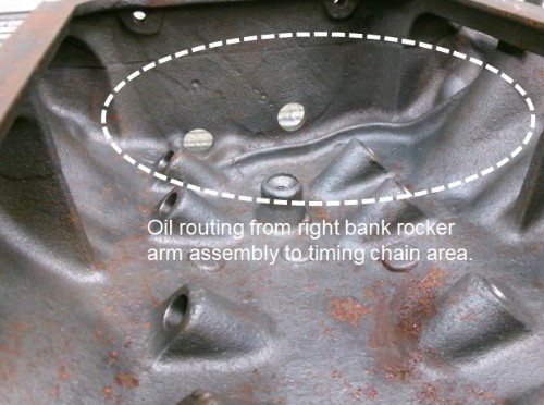
If the right-side rocker arm overflow tube is blocked, there will be very little oil from the rocker arms making its way to the timing chain and gears. The 3° angle on the engine in conjunction with the raised casting in the block at the front of the valley area will prevent top end oil from flooding the front area of the valley where it can then find its way to the timing chain. The lifters will still get oil from the ‘dribble’ that comes down the pushrods. If it’s any consolation, the Ford Y was one of the few engines made that even considered using oil other than leakage from the front cam bearing to provide additional oil to the timing chain and gears. Still, if aiming for300K miles without the timing chain and gears just flat wearing out, some extra oil in that area will definitely help.
Lorena, Texas (South of Waco)
|
|
|
|
|
FORD DEARBORN
|
|
|
Group: Forum Members
Last Active: 2 days ago
Posts: 802,
Visits: 113.5K
|
Ted, maybe I missed it in your explanation above but if the right side overflow tube is eliminated, I therefore have to believe there will still be sufficient oil flowing from the forward drainback hole to lubricate the timing chain? I pinched the drainback tubes about 60% on the engine I'm presently running to add "some" pressure to the rocker assemblies yet still maintained some flow down the trough for the timing chain. I probably should have fully pressurized the rocker assemblies - something to keep in mind for future builds. Thanks for the information regarding the MEL engine. Brings back memories when I did some modifications to a 383 and installed it in a 62 Galaxie in the 60's but that would be a story for a new thread. Great info, thanks again.
64F100 57FAIRLANE500
|
|
|
|
|
KULTULZ
|
|
|
Group: Forum Members
Last Active: Last Month
Posts: 1.8K,
Visits: 306.4K
|
Ted, Every-time I read one of your posts it's like being in advanced auto theory class. Never seen anything like it and is muchly appreciated and respected. I too am concerned with the magazine shutting down. The amount of TECH INFO that is going to be lost to the hobby is going to be staggering, especially to newcomers. I wish I knew of a way to save it but it all is far beyond me. It reminds me of the closing of the 1954 FORD WEBSITE, invaluable information being lost and forgotten. Again, THANX for all of the above information.
____________________________
|
|
|
|
|
Ted
|
|
|
Group: Administrators
Last Active: Yesterday
Posts: 7.5K,
Visits: 205.9K
|
KULTULZ (7/3/2025)
I can understand pressurized rocker shafts (along with slots) to prevent rocker arm and shaft wear (hopefully).
What I don't understand is completely blocking off the oilers at the end of the shafts meant for timing chain and distributor drive lubrication.My thoughts on the subject. Unless the overflow tubes are completely blocked off, then the rocker arm shafts are not truly pressurized. Opinions are varied on pressurizing the rocker arms shafts though. With the aftermarket roller rocker arms with their bronze bushings, I prefer that those be fully pressurized. Stock engines tend to work either way but my own preference is to leave the overflow tubes intact and functional on those. While blocking off the rocker shaft overflow tube on the left side of the engine does do away with that particular flow of oil, there’s already of good amount of oil already at that location simply due to forward forces of the vehicle when in motion and the 3° rearward slant of the engine. That left side overflow tube was also the result of being able to use a right-side rocker arm assembly without having to make it a different part number assembly. That simplified both the engine assembly process and any service work that had to be performed later. The dedicated routing of the oil from the right-side rocker arm shaft to the timing chain area makes the Ford Y one of the few engines to have this specific feature. What makes that routing unique is the casting within the block at the front of the valley area that directs the oil to the timing chain area. All subsequent engine families produced after the Ford Y simply relied on leakage past the front cam bearing to supply oil to the timing set.
Lorena, Texas (South of Waco)
|
|
|
|
|
Ted
|
|
|
Group: Administrators
Last Active: Yesterday
Posts: 7.5K,
Visits: 205.9K
|
KULTULZ (7/18/2025)
I didn't mean for a right-a-way answer as I know you must be busy, but it is greatly appreciated. Busy on my end is subjective as I’m typically always doing something. With the demise of The Y-Block Magazine, I did get out of the mode of writing regularly scheduled magazine articles. An occasional long forum response helps to restore some of that. There are some magazine articles that never did get published and I do plan on posting those on my website in the near future. I will post the links to those on the YBF forums when that happens. So you machined your own intake adapter plates? The intake manifold adapter plates started out as some aluminum castings from Slovers and then completed here for the Bonneville engine. Those castings did save some time as the basic port openings were already in place. The port intake alignment of the MEL is very similar to that of the 385 series (429/460) so that helps with intake manifold selection. What CI did it finally arrive at? The engine ended up at 370.8 cubic inches using a 3.125” stroke crankshaft. When building engines for the ‘C’ class, it’s preferable to target for at least two less than the maximum required. The ‘C’ class requires that the cubic inches be less than 373 so the build target is 370/371. When getting checked for cubic inch displacement, a cylinder will be checked doing an air volume test. Due to variances in air density and temperature, that air pump/volume test is only accurate to within a couple of cubic inches. If building the engine to the max number available (372.99”) and it fails the air pump test, then the engine would have to be torn down for actual bore and stroke measurements. You really do not want to go down the tear down road in a salty environment if you can avoid it. Been there, done that. Speedway Engine Cubic Inch Tester Tool Was it dynoed? The engine was dynoed and it left the shop ‘pig’ fat on the fuel mixture. That’s a discussion best reserved for another time as it’s another topic all its own. But in this condition, the engine makes a solid 560 HP at the shop altitude of ~660 foot and being overly rich. Bonneville is approximately ~4400 foot above sea level so that gives you something to think about. You take in a lot of MEL work or did you do that as a favor? Parts for M-E-L engines are next to non-existent so I try to not take on these kinds of builds very often. Besides cam core availability, even main bearings and cam bearings are an issue for this family of engines. But they are a challenge so if Keith wants to run a MEL engine, I’m game. He claims an ‘Edsel’ engine on the entry so there’s some novelty with that. There is a 385 series engine in the works for this class and that engine should prove to be almost too easy when it comes to parts availability.
Lorena, Texas (South of Waco)
|
|
|
|