|
By lalkie - Last Year
|
|
I read about altering the rocker shaft to improve oiling. I haven't been able to find the article again. Can someone point me to the article? Thanks Larry
|
|
By 55blacktie - Last Year
|
|
yblockguy.com Tech Tips
|
|
By Ted - Last Year
|
Here’s the link to a past thread that provides links to various threads or discussions on the subject.
http://forums.y-blocksforever.com/FindPost153971.aspx
If simply looking for the thread regarding ‘slotting’ the oil holes in the rocker arm shafts, here is the link to that one.
http://forums.y-blocksforever.com/FindPost7000.aspx
|
|
By KULTULZ - Last Year
|
TED,
I remember reading your thoughts and displeasure on the below lube designs. I would think it would solve the problem(s).
|
|
By KULTULZ - Last Year
|
|
BTT
|
|
By Ted - Last Year
|
In reference to the above pictures, there are those engine builders out there that do not perform the necessary research into a perceived problem before just applying a ‘shoot from the hip’ fix. The problem with the internet and social media is that all these fixes get posted by people who are not experts in their respective fields, but these fixes get accepted and approved by the masses.
Having pulled apart several Ford Y engines with over 300K miles on them and still having the stock oiling systems doing their job, I question some of those fixes that involves adding extra oil lines. Even my own ’55 Ford with well over 300K miles on it still has the stock oiling system and is still doing as Ford originally intended. The key to that one is scheduled oil changes along with what I would call a quality 10W-40 oil. That engine has been on the same 10W-40 since it was first purchased in late 1954.
The latest crop of soft cam bearings does bring to the forefront the issue of the center cam journal meshing into the bearing and shutting off the top end oil supply. There are several fixes for that without going to the trouble of rerouting the oil thru auxiliary oil lines. Some of those fixes include machining the camshaft center groove deeper, using a cam bearing with the oil groove on the O.D. of the bearing, or simply adding another groove in the block behind the center cam bearing that allows oil to flow to the top end without having to circumvent the existing groove in the camshaft.
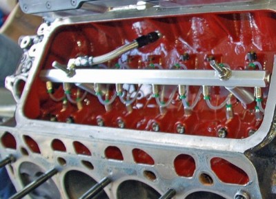
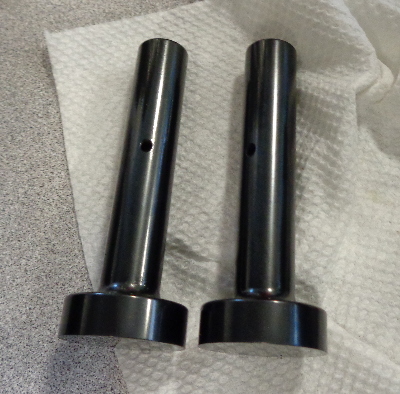
Here are some pictures where additional oil lines are routed to each lifter (tappet) and in this case, special lifters were made in which to pass that rerouted oil thru them. This one was not mine as I’ve only gone so far as to simply put a groove in the block behind the cam bearing which suffices for the majority of Y builds that I do regardless of if they are simply a stock, street performance, or a racing engine. This takes care of the problem with using the softer babbit cam bearings.

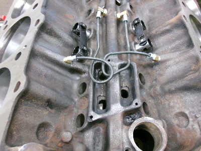
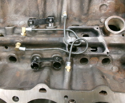
With all that being said, here’s are pictures of what I had to do recently for a M-E-L engine. This plumbing was necessary to provide oil to the top end of the engine as a result of eliminating the oil going to the lifters. Eliminating the oil to the lifters did away with 16 oil leaks in the system. What is not seen in the pictures are the four plugs in various passages to keep the oil flow from reaching the lifters. The 1961 M-E-L block in this case did not cooperate in making the oil galleys larger in diameter so the alternate fix is an effort to provide more oil to the main and rod bearings. This engine is using a solid roller camshaft so oil to the lifters is not a necessary requirement.
|
|
By KULTULZ - Last Year
|
THANX! TED for the explanation.
I agree with lack of proper service intervals and poor quality lubricants.
You think you are saving money but you are actually not.
Interesting on the MEL.
|
|
By alanfreeman - Last Year
|
|
I agree with Ted. I have four cars, all with low mileage or rebuilt Y-Blocks. I have had these same cars for nearly 40 years and have always run them on modern multi-grade detergent oil. I have two early 60's 292's, a 239 and a 256. They are all "bone stock" with no modification to the lubrication system and none of them have ever had an oiling problem. Back in the 50's the oil available was non-detergent and I think that it was that type of oil which clogged the passages and resulted in poor oiling to the rockers. With a clean engine following a rebuild, and the use of multi-grade detergent oil, the original lubrication system should work just fine.
|
|
By 55blacktie - Last Year
|
|
According to Howard's Cams, their Y-block cam's center journal oil groove is .020 deep (I've not measured it). I also purchased Schumann's Durabond cam bearings/w the outside groove to which Ted Referred. I intend to use 10w-40 conventional oil. My oil pump is a rebuilt gerotor. I'm considering having the rocker assemblies pressurized. Based on what I've just read, it sounds like it isn't necessary. Any other suggestions/recommendations?
|
|
By KULTULZ - Last Year
|
Detergent engine oils were being introduced in the fifties. Prior to that, non detergent was used usually without a filter. It had no detergents/dispersants and when returned to the pan, most trash/carbon would fall out of suspension and remain in the pan. The service interval on non-detergent was also more frequent.
Inadequate crankcase ventilation (ROAD DRAFT) only compounded the situation. If you notice on FORD NEW CAR OPTIONS (1950's FORD) a 'FULL-FLOW FILTER' was offered but there was an additional charge. So rule of thumb was to use non-detergent w/o filtering (no use as there was no dispersant package) and detergent with an oil filter.
I remember (as a young and aspiring 're-fueling technician') that most customers had no concern for quality and just said throw the cheapest thing in (oil change on the front). There were premium oils available.
|
|
By KULTULZ - Last Year
|
I can understand pressurized rocker shafts (along with slots) to prevent rocker arm and shaft wear (hopefully).
What I don't understand is completely blocking off the oilers at the end of the shafts meant for timing chain and distributor drive lubrication.
|
|
By KULTULZ - Last Year
|
"With all that being said, here’s are pictures of what I had to do recently for a M-E-L engine. This plumbing was necessary to provide oil to the top end of the engine as a result of eliminating the oil going to the lifters.
Eliminating the oil to the lifters did away with 16 oil leaks in the system. What is not seen in the pictures are the four plugs in various passages to keep the oil flow from reaching the lifters. The 1961 M-E-L block in this case did not cooperate in making the oil galleys larger in diameter so the alternate fix is an effort to provide more oil to the main and rod bearings. This engine is using a solid roller camshaft so oil to the lifters is not a necessary requirement."
TED -
This is the same MEL you were searching for inserts?
When you have some extra time ( ), can you go into more detail the modifications you performed (similar to an FE center oiler - solids?), why and what did the customer use the engine for (driver - hot street - competition). ), can you go into more detail the modifications you performed (similar to an FE center oiler - solids?), why and what did the customer use the engine for (driver - hot street - competition).
SOLID ROLLER on a MEL? Man must have been serious.
This was a 1961 block?
As always, THANX for sharing your knowledge and expertise.
|
|
By Ted - Last Year
|
Kultulz. This should answer most of your questions.
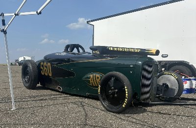
This is the same engine that I was needing a specific main bearing for. And I did find the bearings. The rod bearings are BBC as the Mercury 383 crankshaft must be destroked anyhow to fit the ‘C’ engine class for Bonneville. The car itself is configured for the AIR (American Iron Roadster) class. While destroking the crankshaft, the rod journals are reduced to the BBC 2.200” size. The factory MEL rod journal size is 2½” so there’s a lot to work with here. By luck of the draw, the journal width for the MEL is exactly the same size as the BBC which allows BBC connecting rods to be used without any accompanying rod or journal modifications other than just reducing the journal size. An aftermarket 7.100” long BBC H-Beam connecting rod is being used due the extreme shortness on the stroke and the need to get the wrist pin back in a position closer to the top of the piston. A single plane intake manifold for a 460 Ford with a 1050 cfm carburetor takes care of the induction chores. Fabricated spacers adapts the 460 Ford manifold to the M-E-L heads. The heads are from the 462 engines which have smaller intake ports than the 383, 410, and 430 heads. The 462 heads outflow the earlier heads significantly due to the improved short turn radius in the heads. That is a result of maintaining the same intake port dimension at the top of the port but making the intake ports shorter overall which helps the short turn radius.
The camshaft is a 1961 Isky roller grind that was a new, never used, camshaft when the Bonneville MEL project was hatched. This particular camshaft uses the stepped cam bearings similar to what you find in the SBF engines. While the roller lifters for the M-E-L are the same diameter as the LYB, FE, SBF (289, 302, 351W), 335 series (351C), 385 series (429/460), and others, the tie bar that connects the lifter pairs had to be longer due to the lifter bore spacing being wider in the MEL engines than the others. But with some perseverance, longer tie bars were located that would work with the lifters that were being used.
The block that was pictured is a ’61 430 block and it’s the one that is in the car right now. Keith Cornell fabricated his own steel bellhousing that allows the 5 speed manual transmission to be used behind those 1961 and later blocks. Hence the reason an earlier block with the standard FE bellhousing pattern was not used as the car was originally set up with the 462 block thinking that the larger bore size would help the cylinder head flow. I had previously drilled the oil galleys larger in the 462 blocks without issue but the two 430 blocks that I tried to do the same oil galley enlargement did not like that as the enlarged oil pump to filter hole would break through the casting on the inside of the block. I eventually just sleeved the holes back to the stock size and then decided to simply stop the sixteen oil leaks at the lifter holes to help supply enough oil to the bottom end of the engine for extended full throttle running.
The idea behind using the 430 block instead of the prior 462 block was to capitalize on the smaller bore size which would allow a corresponding increase in stroke and still be within the rules. The horsepower with the previous combination (larger bore, shorter stroke) was at a plateau and was running just shy of 200 mph. At this point and because the previous engine had dropped a valve and destroyed the block, it was decided to just increase the torque by increasing the stroke. To keep the cubic inches within the rules, the smaller bore size after boring dictated what the new and longer stroke would be. Some algebra took care of that calculation and the 383 crankshaft was destroked accordingly. If an Edsel 410 block had been available, that would have been even better as the bore on those is 4.200” versus the 4.300” on the 430 blocks. As it was, there was a nice increase in both the horsepower and torque but it does come in at a much earlier rpm now.
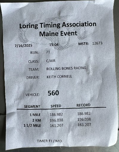
The car did some shake down runs at the Loring, Maine track just a couple of days ago and it looks promising for running 200 MPH plus at Bonneville. Bonneville does happen again starting in a couple of weeks. Here are pics of both the car and a timing slip at the Loring, Maine track.
|
|
By KULTULZ - Last Year
|
DAMN!!!Ask and 'ye shall receive ...
I didn't mean for a right-a-way answer as I know you must be busy, but it is greatly appreciated.
So you machined your own intake adapter plates?
What CI did it finally arrive at? Was it dynoed?
You take in a lot of MEL work or did you do that as a favor?
Again, thank you very much. |
|
By Ted - Last Year
|
|
KULTULZ (7/18/2025)
I didn't mean for a right-a-way answer as I know you must be busy, but it is greatly appreciated.
Busy on my end is subjective as I’m typically always doing something. With the demise of The Y-Block Magazine, I did get out of the mode of writing regularly scheduled magazine articles. An occasional long forum response helps to restore some of that. There are some magazine articles that never did get published and I do plan on posting those on my website in the near future. I will post the links to those on the YBF forums when that happens.
So you machined your own intake adapter plates?
The intake manifold adapter plates started out as some aluminum castings from Slovers and then completed here for the Bonneville engine. Those castings did save some time as the basic port openings were already in place. The port intake alignment of the MEL is very similar to that of the 385 series (429/460) so that helps with intake manifold selection.
What CI did it finally arrive at?
The engine ended up at 370.8 cubic inches using a 3.125” stroke crankshaft. When building engines for the ‘C’ class, it’s preferable to target for at least two less than the maximum required. The ‘C’ class requires that the cubic inches be less than 373 so the build target is 370/371. When getting checked for cubic inch displacement, a cylinder will be checked doing an air volume test. Due to variances in air density and temperature, that air pump/volume test is only accurate to within a couple of cubic inches. If building the engine to the max number available (372.99”) and it fails the air pump test, then the engine would have to be torn down for actual bore and stroke measurements. You really do not want to go down the tear down road in a salty environment if you can avoid it. Been there, done that.
Speedway Engine Cubic Inch Tester Tool
Was it dynoed?
The engine was dynoed and it left the shop ‘pig’ fat on the fuel mixture. That’s a discussion best reserved for another time as it’s another topic all its own. But in this condition, the engine makes a solid 560 HP at the shop altitude of ~660 foot and being overly rich. Bonneville is approximately ~4400 foot above sea level so that gives you something to think about.
You take in a lot of MEL work or did you do that as a favor?
Parts for M-E-L engines are next to non-existent so I try to not take on these kinds of builds very often. Besides cam core availability, even main bearings and cam bearings are an issue for this family of engines. But they are a challenge so if Keith wants to run a MEL engine, I’m game. He claims an ‘Edsel’ engine on the entry so there’s some novelty with that. There is a 385 series engine in the works for this class and that engine should prove to be almost too easy when it comes to parts availability.
|
|
By Ted - Last Year
|
|
KULTULZ (7/3/2025)
I can understand pressurized rocker shafts (along with slots) to prevent rocker arm and shaft wear (hopefully).
What I don't understand is completely blocking off the oilers at the end of the shafts meant for timing chain and distributor drive lubrication.
My thoughts on the subject.
Unless the overflow tubes are completely blocked off, then the rocker arm shafts are not truly pressurized. Opinions are varied on pressurizing the rocker arms shafts though. With the aftermarket roller rocker arms with their bronze bushings, I prefer that those be fully pressurized. Stock engines tend to work either way but my own preference is to leave the overflow tubes intact and functional on those.
While blocking off the rocker shaft overflow tube on the left side of the engine does do away with that particular flow of oil, there’s already of good amount of oil already at that location simply due to forward forces of the vehicle when in motion and the 3° rearward slant of the engine. That left side overflow tube was also the result of being able to use a right-side rocker arm assembly without having to make it a different part number assembly. That simplified both the engine assembly process and any service work that had to be performed later.
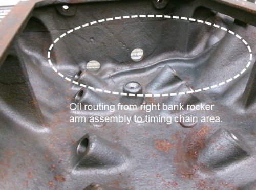
The dedicated routing of the oil from the right-side rocker arm shaft to the timing chain area makes the Ford Y one of the few engines to have this specific feature. What makes that routing unique is the casting within the block at the front of the valley area that directs the oil to the timing chain area. All subsequent engine families produced after the Ford Y simply relied on leakage past the front cam bearing to supply oil to the timing set.
|
|
By KULTULZ - Last Year
|
Ted,
Every-time I read one of your posts it's like being in advanced auto theory class. Never seen anything like it and is muchly appreciated and respected.
I too am concerned with the magazine shutting down. The amount of TECH INFO that is going to be lost to the hobby is going to be staggering, especially to newcomers. I wish I knew of a way to save it but it all is far beyond me.
It reminds me of the closing of the 1954 FORD WEBSITE, invaluable information being lost and forgotten.
Again, THANX for all of the above information.
|
|
By FORD DEARBORN - Last Year
|
|
Ted, maybe I missed it in your explanation above but if the right side overflow tube is eliminated, I therefore have to believe there will still be sufficient oil flowing from the forward drainback hole to lubricate the timing chain? I pinched the drainback tubes about 60% on the engine I'm presently running to add "some" pressure to the rocker assemblies yet still maintained some flow down the trough for the timing chain. I probably should have fully pressurized the rocker assemblies - something to keep in mind for future builds. Thanks for the information regarding the MEL engine. Brings back memories when I did some modifications to a 383 and installed it in a 62 Galaxie in the 60's but that would be a story for a new thread. Great info, thanks again.
|
|
By Ted - Last Year
|
|
If the right-side rocker arm overflow tube is blocked, there will be very little oil from the rocker arms making its way to the timing chain and gears. The 3° angle on the engine in conjunction with the raised casting in the block at the front of the valley area will prevent top end oil from flooding the front area of the valley where it can then find its way to the timing chain. The lifters will still get oil from the ‘dribble’ that comes down the pushrods. If it’s any consolation, the Ford Y was one of the few engines made that even considered using oil other than leakage from the front cam bearing to provide additional oil to the timing chain and gears. Still, if aiming for300K miles without the timing chain and gears just flat wearing out, some extra oil in that area will definitely help.
|
|
By Hoosier Hurricane - Last Year
|
|
Ted, was it you or someone else that drilled a small hole into the oil feed passage to the front cam bearing that dribbled oil (or maybe even a small stream) to the front face of the block above the crank gear to spill oil onto the timing gears? I remember reading that somewhere, but I forgot where I saw it.
|
|
By cos - Last Year
|
|
Very interesting info Ted. Lots of problem solving and looking for parts to make it work. thanks for sharing.
|
|
By FORD DEARBORN - Last Year
|
Very good information - glad I didn't completely eliminate this supply of oil to the timing chain. When assembling my engine and before the timing chain cover was installed, I slapped on the oil pan with a couple bolts, added a couple quarts oil and with an assistant, spooled up the oil pump with a drill motor and made a short video showing the oil flowing along the valley trough down to the crank sprocket. It is a '64 block but I added the "tin" trough (54-55 style) below and to the left of the cam sprocket. I wish I could share that interesting video with everyone here because it clearly shows a very small but steady stream of oil spilling onto the crank sprocket where the chain engages.
|
|
By Ted - Last Year
|
|
Hoosier Hurricane (7/21/2025)
Ted, was it you or someone else that drilled a small hole into the oil feed passage to the front cam bearing that dribbled oil (or maybe even a small stream) to the front face of the block above the crank gear to spill oil onto the timing gears? I remember reading that somewhere, but I forgot where I saw it.
John.
That was Tim McMaster that originally came up with the idea of taking pressurized oil from the from the front cam bearing and redirecting it to the timing chain.
He originally posted that process on this site showing how to drill a new hole behind the cam thrust plate and then grooving the backside of the cam thrust plate to redirect that oil to the timing chain. Unfortunately, some of the pictures within that original post did not stay with the post when the forums were moved from one server to another during an upgrade. But deeper within that same post are some pictures that will help to explain the process. Here’s the link to that original post and also the post with the pictures.
http://forums.y-blocksforever.com/FindPost24720.aspx
http://forums.y-blocksforever.com/FindPost148707.aspx
Here’s the link to that modification as posted on Tim McMaster’s website.
Tech Tips - Oiling Modifications for Y-Block V8 Timing Chain
|
|
By KULTULZ - Last Year
|
|
Thanks for the information regarding the MEL engine. Brings back memories when I did some modifications to a 383 and installed it in a 62 Galaxie in the 60's but that would be a story for a new thread.
I for one would be very interested in that info ...
|