|
Author
|
Message
|
|
KULTULZ
|
 Posted 3 Years Ago
|
|
Group: Forum Members
Last Active: 3 days ago
Posts: 1.9K,
Visits: 306.5K
|
- ASKING FOR A FRIEND -
[QUOTE=metro1;2268638] I removed the heads from another engine and had them reworked at the machine shop. I was installing them today and ran into something I had not experienced before. On the drivers side head the top holes in the head do not exactly line up with the threaded holes in the block. The bolts drag against the front of the holes in the head. I tried it back on the old engine and the same thing. It must be bored wrong. The bolts will go in but the drag will make torqueing it incorrect. I am using ARP bolts which have a smaller shaft diameter except for the top 5/16 so they only scrape there. At this point I could shave a few thousands off of the top part of the bolts but I really don't want to do that. I guess I could open up the front top of the holes in the head. Has anyone ever ran into this? THREAD SOURCE - https://www.fordbarn.com/forum/newreply.php?do=newreply&p=2268638[/quote]
____________________________
|
|
|
|
|
DryLakesRacer
|
|
|
Group: Forum Members
Last Active: 4 days ago
Posts: 1.7K,
Visits: 340.1K
|
If the head sits on the dowels correctly I would slightly enlarge the holes and use hardened arp type washers on the fasteners. I’ll bet .005” would probably do it. Since they are cast iron a die grinder with an extended shank tool would do the same thing. My father owned a machine shop and was a wind tunnel model maker but I saw him fix a friends head with a similar problem. He clamped a head to the Bridgeport mill table, put a cutting tool that looked like a reamer and cut the side of the hole that hit a bolt. Also it’s possible to put studs on the top row a slide the head over them or if there are Allen ends on them put them in with all the other fasteners in but not tight.
There are many ways to fix this without distorting the torque.
56 Vic, B'Ville 200 MPH Club Member, So Cal.
|
|
|
|
|
Ted
|
|
|
Group: Administrators
Last Active: 3 days ago
Posts: 7.6K,
Visits: 206.0K
|
I run into this when angle milling the heads. At a 2° angle change, the head bolt holes in the heads are no longer perpendicular to the threaded holes in the block and are off significantly at the top of the heads. At a two-degree head deck angle change, the head bolts will not come close to starting into the block. For these, I have to machine the head bolt holes with an end mill at the appropriate angle so it elongates the head bolt hole at the top of the head while not changing the hole dimension at the bottom of the head. And then the head bolt holes at the top of the head (both the long and the short) must be refaced so that they are square with the holes. From the description you give for the friend’s cylinder head, it was resurfaced without care to ensure that the deck surface was square to the grinding or cutting tool when the head was resurfaced. If that is indeed the case, then the angle between the head surface and the intake mating surface will be different. If one cylinder head bolts down fine, then use that angle as a comparison to the deck to intake angle on the head that’s having a head bolt issue. Another telltale would be if the head bolt hole at the bottom of the head is not square with the deck surface of the head. A machined bar that fits the head bolt hole at the bottom of the head would help to determine that either with some layout dye or a square or a dial indicator. Several options there.
  Lorena, Texas (South of Waco) Lorena, Texas (South of Waco)
|
|
|
|
|
KULTULZ
|
|
|
Group: Forum Members
Last Active: 3 days ago
Posts: 1.9K,
Visits: 306.5K
|
- THANK YOU GENTLEMEN! - Didn't need to hear about the intake not sitting down correctly ...  How difficult to 'square' the cyl head ($$$) (if it is the cyl head) ?
____________________________
|
|
|
|
|
Ted
|
|
|
Group: Administrators
Last Active: 3 days ago
Posts: 7.6K,
Visits: 206.0K
|
|
|
|
|
|
Hoosier Hurricane
|
|
|
Group: Moderators
Last Active: Yesterday
Posts: 3.7K,
Visits: 323.7K
|
Kultulz said that the bolts drag on the front side of the holes. That would indicate that the head is milled crooked end to end. A quick and dirty way to check this would be to measurer the pads on the lower side of the head and compare them end to end. He could also CC the chambers and see if they vary from one end to the other.
John - "The Hoosier Hurricane"

|
|
|
|
|
KULTULZ
|
|
|
Group: Forum Members
Last Active: 3 days ago
Posts: 1.9K,
Visits: 306.5K
|
I wanna thank you guys again. If this happened to me I would have had a heart attack ... 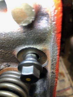
____________________________
|
|
|
|
|
Ted
|
|
|
Group: Administrators
Last Active: 3 days ago
Posts: 7.6K,
Visits: 206.0K
|
Hoosier Hurricane (11/11/2023)
Kultulz said that the bolts drag on the front side of the holes. That would indicate that the head is milled crooked end to end. A quick and dirty way to check this would be to measurer the pads on the lower side of the head and compare them end to end. He could also CC the chambers and see if they vary from one end to the other.John. Thanks for pointing out that the bolts are dragging on the front side of the holes. I totally missed that in reading the original post. The intake to deck angle is likely okay in that case but still could present an intake gasket sealing problem from front to rear on that particular head. Cc’ing the combustion chambers would confirm that the head was simply milled more in an end-to-end fashion rather than more in a intake to exhaust side fashion. Using the math on the difference in the combustion chamber sizes would give a good indication on how much the end of the head with the larger combustion chambers would need to be milled to get the end with the larger chamber even with the end of the head with the smaller chamber. Still a simple fix in remilling the head again and this time getting the deck square with the head bolt holes.
Lorena, Texas (South of Waco)
|
|
|
|
|
Ted
|
|
|
Group: Administrators
Last Active: 3 days ago
Posts: 7.6K,
Visits: 206.0K
|
Kultulz. It would be good to know what the head casting number is. Knowing that and the combustion chamber sizes would be helpful in determining how much the head would need to be remilled to correct the difference in combustion chamber sizing.
Lorena, Texas (South of Waco)
|
|
|
|
|
KULTULZ
|
|
|
Group: Forum Members
Last Active: 3 days ago
Posts: 1.9K,
Visits: 306.5K
|
10-4. Let me see if I can get it. It belongs to a poster over@ FORDBARN.
____________________________
|
|
|
|