|
Group: Administrators
Last Active: 48 minutes ago
Posts: 7.6K,
Visits: 206.0K
|
The Eaton Balancing Y entry fought me most of the week but it’s now turned into a serious performer. Today will be spent taking care of some loose ends such as bracket for the MSD box and coil and some kind of bracket for the throttle utilizing a Morse cable. Once the engine is fired one last time to insure that the changes are as needed, it comes off the dyno, oil drained, and put on an engine cradle for transportation. The team heads out for Lima, Ohio early Monday morning. The engine will be teched in on Wednesday and ran on Thursday. My engine is number 4 on the run order list while Jon Kaase’s entry is #5 and Royce’s is #6. Details on my engine particulars will not be available until after the competition for the obvious reasons.
  Lorena, Texas (South of Waco) Lorena, Texas (South of Waco)
|
|
Group: Forum Members
Last Active: 8 Years Ago
Posts: 1.6K,
Visits: 5.2K
|
Go Get em Ted!
 55 Vicky & customline 58 Rack Dump, 55 F350 yard truck, 57 F100 59 & 61 P 400's, 58 F100 custom cab, 69 F100, 79 F150, 82 F600 ramp truck, 90 mustang conv 7 up, 94 Mustang, Should I continue?
|
|
Group: Forum Members
Last Active: 2 Years Ago
Posts: 1.3K,
Visits: 9.2K
|
The Best of Luck Ted!
-Gary Burnette-
|
|
Group: Forum Members
Last Active: 6 Years Ago
Posts: 435,
Visits: 29.3K
|
Smoke em Ted!!
Rowen
55CV
Woodland, Ca
|
|
Group: Forum Members
Last Active: Last Month
Posts: 918,
Visits: 7.5K
|
Good luck Ted, sounds like the engine is a runner. Hopefully we can get some updates next week. I'm sure everyone will be interested in whats going on back at UNOH.
http://ford-y-block.com 20 miles east of San Diego, 20 miles north of Mexico 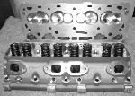
|
|
Group: Forum Members
Last Active: 10 Years Ago
Posts: 152,
Visits: 1.1K
|
Good luck Ted.
I'm hoping there will be another you tube vid. with another Eaton entry as a winner.
|
|
Group: Forum Members
Last Active: 2 Years Ago
Posts: 884,
Visits: 14.3K
|
Good luck Ted. Can't wait to hear the results.
Durham Missouri
|
|
Group: Forum Members
Last Active: 8 Years Ago
Posts: 691,
Visits: 1.3K
|
Knock their socks off Ted!!!
I love the smell of burning rubber in the morning!
|
|
Group: Forum Members
Last Active: 5 Months Ago
Posts: 204,
Visits: 92.3K
|
I haven't read this whole thread so apologies if someone already did this. Here is a link to event coverage at the Challenge. Hope it works. http://www.hotrod.com/events/engine-masters-challenge/
MplsMike
'56 Parklane
Minneapolis, MN
|
|
Group: Forum Members
Last Active: 2 Years Ago
Posts: 1.3K,
Visits: 9.2K
|
Thanks, excellent read!
-Gary Burnette-
|