|
Group: Forum Members
Last Active: 4 Years Ago
Posts: 726,
Visits: 73.6K
|
All the comments are very helpful and appreciated. Anything to help the reader have a better understanding is very important.
Continuing on what worked for me......
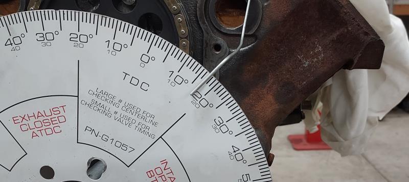
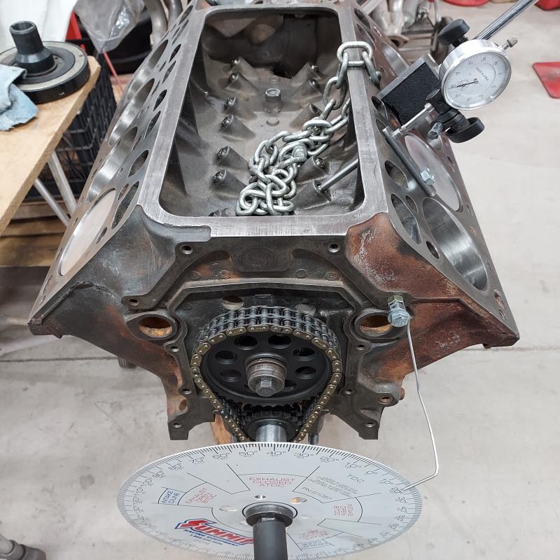
Next was to establish the timing of the intake cam lobe at .050" lift. Moving my little jig over to the intake lifter, I rotated the crank to allow the lifter to be on it's heel where there is no lift. I then set the dial indicator on the shortened push rod with some preload to insure constant contact. With pressure applied to the lifter by the screwdriver, to assure a correct reading, again I set the indicator to 0 and continued rotating the crank clockwise (natural engine rotation) until the lobe began to make it's lift and the indicator started it's move towards .050". With pressure applied to the lifter, I continued to rotate the crank until .050" was reached on the indicator. A look at the pointer on the degree wheel read 17° before top dead center (BTDC).
A glance at the cam card and I was excited to see that it should be 17° BTDC.
Charlie Burns Laton, Ca (South of Fresno)
BurnsRacing981@gmail.com
|
|
Group: Forum Members
Last Active: 4 Years Ago
Posts: 726,
Visits: 73.6K
|
My original goals were all related to comparing the cam degree specs to the cam card. I only wanted to measure the following:
1. The intake and exhaust lifts at .050"
2. The total lift for the intake and exhaust lobes
3. The cam lobe separation angle.
The second set of wanted data was a simple task to measure the total lifts on the lobes. My dial indicator was already setup to do this on the intake lobe when I measured the timing at .050" lift. It was just a matter of continuing the clockwise rotation of the crank until the dial indicator read the highest reading before following the lobe down the other side.
Both the intake and exhaust lobes measured .360" lift. Neither of these matched the cam card??? However, the cam card spec was .361" lift for the intake and .359" lift for the exhaust. A call to the cam grinder set me at ease by telling me it was quite common to be off a thousandths or so in the measuring with a few variables at play when taking these measurements. Positive lifter contact with the lobe, absolute placement of the dial indicator pointer, parallax error in reading analog gauges just to name a few.
Charlie Burns Laton, Ca (South of Fresno)
BurnsRacing981@gmail.com
|
|
Group: Forum Members
Last Active: 4 Years Ago
Posts: 726,
Visits: 73.6K
|
After receiving a number of recommendations to also measure the #6 cylinder against the cam card, I wanted to know exactly why and a call to Ted Eaton was in order.
First, with the #6 and the #1 cylinders sharing the same cam spec measurements on the cam card, it was easy enough to move the dial indicator in position to take these measurements. My findings were not perfect, but within a 1/2° from the card for the exhaust and 1° for the intake. Another call to the cam grinder and he again set my mind at ease by saying something similar to what he had said earlier.
In talking to Ted, if a cam grinder mistake is made, it can happen when the grinding equipment is not changed to meet the specs on different engines. Although the Y-Block is a 90° cylinder block like most are, the lifter bores are not. The Y has an 86° lifter bore spread while a small block Che** has a spread of 82°. You can see that from time to time the operator might not remember to make the change when grinding the Y cam. Taking the specs on the number 6 cylinder catches this.
Charlie Burns Laton, Ca (South of Fresno)
BurnsRacing981@gmail.com
|
|
Group: Forum Members
Last Active: 3 Years Ago
Posts: 1.1K,
Visits: 58.8K
|
It's really great that Ted was able to share that kind of info with you and in turn all of us.
A L A N F R A K E S ~ Tulsa, OK
|