|
Author
|
Message
|
|
Ted
|
|
|
Group: Administrators
Last Active: Yesterday
Posts: 7.5K,
Visits: 205.8K
|
DiLL (2/2/2022)
Joe, would you mind sharing the specs on the forged pistons you ordered from JE? I'm in the process of trying to get my pistons ordered and would like a reference. If for competitive reasons you're unable to I understand. thanks! 55blacktie (2/2/2022)
Joe, does that include forged flat-tops/w no valve reliefs and metric rings for EBU and C2 rods? Thanks. Because there were some questions regarding piston ordering asked in a different and somewhat unrelated thread, I have started this post specific to ‘Custom Pistons’. When ordering custom pistons, the piston rings are the first consideration and are ordered prior to ordering the pistons. Piston rings are not available as an ‘off the shelf’ item for every possible bore size so the bore size must be determined first. Depending upon the availability, it may be necessary to juggle the bore size in order to get the ring width sizes you are looking for. Because of the many small bore metric sized pistons that are available, there are a number of cylinder bore size options but these may not fall in the normal 0.020, 0.030, 0.040” sizes that are typical to the American engines. In some cases, the final bore size may fall into ranges between those numbers. When the rings are ordered, you will need the bore size, ring thickness, and radial depth numbers for those rings so that the pistons can be machined specifically for those rings. A word of caution about ring thickness. As the rings get thinner, the cylinder wall finish gets more critical.
  Lorena, Texas (South of Waco) Lorena, Texas (South of Waco)
|
|
|
|
|
DryLakesRacer
|
|
|
Group: Forum Members
Last Active: Last Month
Posts: 1.7K,
Visits: 340.1K
|
Ted is right on with custom pistons. I’ve ordered way to many and was told in the 70’s by Nick Arias who made 90% of my racing GMC 6 piston to purchase to the ring package and forget the bore as it will be dictated by the piston/ring combo and the pistons were always custom to our engine but standard to others. Pin height, crowns, skirts, etc were not rocket science to them. I still like 1/16-1/16-3/16” for street use but have moved thinner on both our V8 and 6’s we race. Just like head gaskets have changed dictating the surface machined on the block and heads. Thanks Ted for all you share..
56 Vic, B'Ville 200 MPH Club Member, So Cal.
|
|
|
|
|
DiLL
|
|
|
Group: Forum Members
Last Active: 3 Years Ago
Posts: 29,
Visits: 17.6K
|
Ted, thank you for starting this thread. I've attached a copy of the JE Pistons order form to use as a reference for questions myself and others might have. For the most part the form seems very self explanatory until I got to the camshaft section where it says "degreed in std +-" is this in reference to cam advance and retard? My second question is how to find your valve lift at TDC. Is this something that can be calculated based off of the cam card specs alone? My last question is in regard to the piston rings themselves; Axial and radial thickness as well as distance from the piston crown. From my readings, it seems lots of people are going to thinner metric rings packs as they can aid in less weight, friction, etc. My question is, what axial and radial thickness best suit an N/A engine? What size is best for a power adder turbo, nitrous, supercharger? Will the thin metric rings hold up to boost or would a more conventionally sized 1/16, 3/16 ring pack be best when more pressure from boost? How much piston crown is needed for N/A vs boost?
DiLL
|
|
|
|
|
Ted
|
|
|
Group: Administrators
Last Active: Yesterday
Posts: 7.5K,
Visits: 205.8K
|
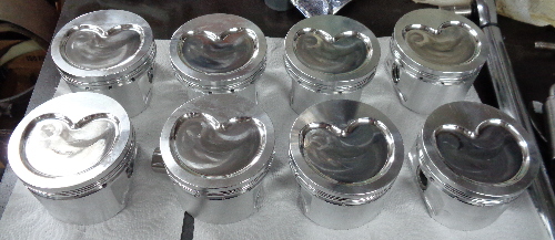
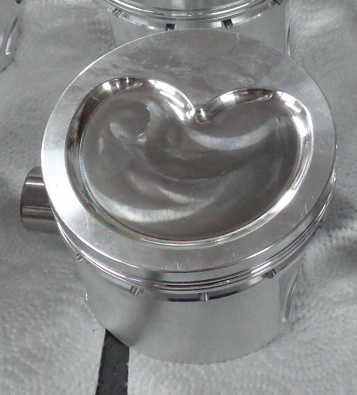
Miles. I have not needed the cam specs when ordering pistons. But that ‘Degreed in STD °’ section on the order form is likely referring to the advance or retard for the camshaft. I doubt that information is going to provide the piston manufacturer much to go on as the Ford Y is likely not in their files like some of the more main stream engines. For flat top pistons and advertised valve lifts below 0.535”, valve pockets have not been required. When doing the aluminum heads and going with dish pistons, I do make the dish also accommodate the valves. This same dish would also work for a blower application depending upon the compression ratio and amount of boost. Metric rings are available in a variety of widths with 1.5, 1.2, and 1.0mm being the more common ones to pick from for the top and second rings. 3.0mm for the oil rings is pretty much standard fare and available for most bore sizes. For a boosted street application, I would recommend a 1.5, 1.5, 3.0 set. For the normally aspirated street engines, the 1.2, 1.5, 3.0 and 1.2, 1.2, 3.0mm sets are my preferred choices. If available, go with a ‘napier’ second ring as those give an additional measure of oil control. Stay with the standard oil ring tensions for the metric rings. Radial thicknesses (depths) are pretty much standard but will vary with the thicknesses so you will need to know what they are when ordering the pistons. Here are a couple of pictures of the dished piston design.


  Lorena, Texas (South of Waco) Lorena, Texas (South of Waco)
|
|
|
|
|
Ted
|
|
|
Group: Administrators
Last Active: Yesterday
Posts: 7.5K,
Visits: 205.8K
|
|
|
|
|
|
Ted
|
|
|
Group: Administrators
Last Active: Yesterday
Posts: 7.5K,
Visits: 205.8K
|
When doing the compression ratio calculations, assume nothing. If a particular value was not checked, it’s simply a guess. Crankshaft strokes as well as connecting rod lengths (center to center) should be verified. When checking the crankshaft strokes, check all four journals. It’s not unusual for some variance there. The same goes for the connecting rods; check all eight. Don’t use factory combustion chamber volumes either. They are considered ‘nominal’ on the original factory stock heads meaning that’s the best case or smallest scenario. With any valve jobs and milling during the last half century, there’s no idea where those combustion chamber volumes are without actually measuring. To order the pistons, you’ll need to know what the target deck height is. For the Y, I target for 9.750” which allows for a 0.020” - 0.030” cleanup of the stock decks. If the block has had the decks previously milled, then take that into consideration. Once the target deck height of the block is known, then the wrist pin location (aka compression height) can be calculated. That calculation is: Deck Height – (stroke divided by two) – connecting rod length = wrist pin CH Or Deck Height – ((stroke divided by two) + connecting rod length) = wrist pin CH For the compression ratio example in the prior post, the compression height of the piston looks like this. 9.750 - ((3.3/2) + 6.320) = 1.780”
  Lorena, Texas (South of Waco) Lorena, Texas (South of Waco)
|
|
|
|
|
DiLL
|
|
|
Group: Forum Members
Last Active: 3 Years Ago
Posts: 29,
Visits: 17.6K
|
Ted thank you for sharing, I'll be sure to thoroughly verify all the journals and the c/c on the rods. I was finally able to find a good link for calculating static/dynamic compression ratios and was able to repeat the numbers you had posted. This brings me to another question in regard to piston domes/chamber volume and compression. It seems to be commonly stated that for a pump gas engine the dynamic compression ratio is best kept around 8:1-8.5:1. Given the stats you provided while using a 60cc chamber, I calculated a 9.8:1 static and a 7.99:1 dynamic compression. Is it best practice to mill the heads for increased compression or would you recommend adding a dome to the pistons and leaving the chamber as is? When adding boost to an engine, does dynamic compression stay the same or does it too need to be adjusted/lowered to support the added pressure? I hope I'm asking this in a way that it makes sense. My calculations led me to the following:
301" 60cc chamber, 10cc gasket, zero deck ht, flat top piston, 10 psi
static 9.8:1
Dynamic 7.99:1
Effective: 11.75
DiLL
|
|
|
|
|
Ted
|
|
|
Group: Administrators
Last Active: Yesterday
Posts: 7.5K,
Visits: 205.8K
|
If going with a custom piston, then the preferred choice for altering the compression ratio is to work that change into the piston with a deck height and/or dome/dish configuration. Cylinder head modifications can prove to be extensive depending upon if trying to open up the combustion chambers to reduce the compression ratio or milling to increase the compression ratio. For a normally aspirated engine, 8.2:1 DCR is the recommended maximum but that 8.2:1 number does not leave any room or tolerance for premium grade fuel that is less than advertised. For that reason, it's typically best to target for 8.0:1 DCR to leave just enough latitude for gasoline that may be slightly less than 91 octane with an engine tuned for 91-93 octane fuel. When adding boost to an engine, the compression ratio is being artificially increased so the DCR number must be decreased accordingly. My rule of thumb is to reduce a full point of compression for each half an atmosphere of boost. A full atmosphere of boost is 14.7 psi so half of that would be 7.4 psi so if going with 7-8 psi of boost, then lower the DCR a full compression point. Instead of using the 8.0-8.2 DCR value as used for a normally aspirated engine, target that DCR number for 7.0-7.2 DCR for 8 psi of boost. All these numbers are for readily available pump premium gasoline (91-93 octane) so if using additives or racing fuel, then a higher compression ratio would be sustainable.
  Lorena, Texas (South of Waco) Lorena, Texas (South of Waco)
|
|
|
|
|
Ted
|
|
|
Group: Administrators
Last Active: Yesterday
Posts: 7.5K,
Visits: 205.8K
|
|
|
|
|
|
55blacktie
|
|
|
Group: Forum Members
Last Active: Today @ 2:18:54 AM
Posts: 1.2K,
Visits: 1.8K
|
I'm assuming those 60cc heads are Mummert aluminum heads. If that's so, will the DCR be lower than with iron heads?
|
|
|
|