|
By Ted - 3 Years Ago
|
|
DiLL (2/2/2022)
Joe, would you mind sharing the specs on the forged pistons you ordered from JE? I'm in the process of trying to get my pistons ordered and would like a reference. If for competitive reasons you're unable to I understand. thanks!
55blacktie (2/2/2022)
Joe, does that include forged flat-tops/w no valve reliefs and metric rings for EBU and C2 rods? Thanks.
Because there were some questions regarding piston ordering asked in a different and somewhat unrelated thread, I have started this post specific to ‘Custom Pistons’.
When ordering custom pistons, the piston rings are the first consideration and are ordered prior to ordering the pistons. Piston rings are not available as an ‘off the shelf’ item for every possible bore size so the bore size must be determined first. Depending upon the availability, it may be necessary to juggle the bore size in order to get the ring width sizes you are looking for. Because of the many small bore metric sized pistons that are available, there are a number of cylinder bore size options but these may not fall in the normal 0.020, 0.030, 0.040” sizes that are typical to the American engines. In some cases, the final bore size may fall into ranges between those numbers. When the rings are ordered, you will need the bore size, ring thickness, and radial depth numbers for those rings so that the pistons can be machined specifically for those rings.
A word of caution about ring thickness. As the rings get thinner, the cylinder wall finish gets more critical.
|
|
By DryLakesRacer - 3 Years Ago
|
|
Ted is right on with custom pistons. I’ve ordered way to many and was told in the 70’s by Nick Arias who made 90% of my racing GMC 6 piston to purchase to the ring package and forget the bore as it will be dictated by the piston/ring combo and the pistons were always custom to our engine but standard to others. Pin height, crowns, skirts, etc were not rocket science to them. I still like 1/16-1/16-3/16” for street use but have moved thinner on both our V8 and 6’s we race. Just like head gaskets have changed dictating the surface machined on the block and heads. Thanks Ted for all you share..
|
|
By DiLL - 3 Years Ago
|
Ted, thank you for starting this thread. I've attached a copy of the JE Pistons order form to use as a reference for questions myself and others might have. For the most part the form seems very self explanatory until I got to the camshaft section where it says "degreed in std +-" is this in reference to cam advance and retard? My second question is how to find your valve lift at TDC. Is this something that can be calculated based off of the cam card specs alone? My last question is in regard to the piston rings themselves; Axial and radial thickness as well as distance from the piston crown. From my readings, it seems lots of people are going to thinner metric rings packs as they can aid in less weight, friction, etc. My question is, what axial and radial thickness best suit an N/A engine? What size is best for a power adder turbo, nitrous, supercharger? Will the thin metric rings hold up to boost or would a more conventionally sized 1/16, 3/16 ring pack be best when more pressure from boost? How much piston crown is needed for N/A vs boost?
|
|
By Ted - 3 Years Ago
|
Miles. I have not needed the cam specs when ordering pistons. But that ‘Degreed in STD °’ section on the order form is likely referring to the advance or retard for the camshaft. I doubt that information is going to provide the piston manufacturer much to go on as the Ford Y is likely not in their files like some of the more main stream engines.
For flat top pistons and advertised valve lifts below 0.535”, valve pockets have not been required. When doing the aluminum heads and going with dish pistons, I do make the dish also accommodate the valves. This same dish would also work for a blower application depending upon the compression ratio and amount of boost.
Metric rings are available in a variety of widths with 1.5, 1.2, and 1.0mm being the more common ones to pick from for the top and second rings. 3.0mm for the oil rings is pretty much standard fare and available for most bore sizes. For a boosted street application, I would recommend a 1.5, 1.5, 3.0 set. For the normally aspirated street engines, the 1.2, 1.5, 3.0 and 1.2, 1.2, 3.0mm sets are my preferred choices. If available, go with a ‘napier’ second ring as those give an additional measure of oil control. Stay with the standard oil ring tensions for the metric rings. Radial thicknesses (depths) are pretty much standard but will vary with the thicknesses so you will need to know what they are when ordering the pistons.
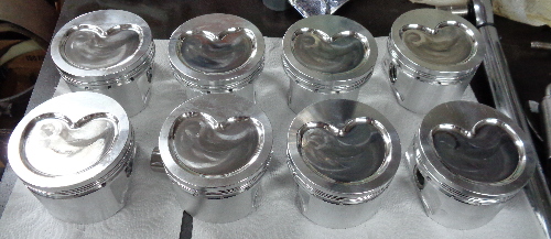
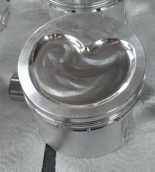
Here are a couple of pictures of the dished piston design.
|
|
By Ted - 3 Years Ago
|
With the rings selected, it must be determined what the top of the piston looks like whether it’s a flat top, dished, or domed. The target compression ratio will help to determine that.
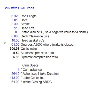
To calculate both the static and dynamic compression ratio, the following pieces of information will be required.
Bore
Stroke
Combustion chamber volume
Head gasket volume
Piston location in relation to the deck
Dome or dish volume
Connecting rod length
Camshaft intake valve closing event
Juggling some of the piston values such as the deck height and piston dome/dish volumes will allow the SCR/DCR numbers to be varied. Once you have the compression ratio numbers in the range you are targeting for, then you’ll get a set of numbers looking like this.
|
|
By Ted - 3 Years Ago
|
When doing the compression ratio calculations, assume nothing. If a particular value was not checked, it’s simply a guess. Crankshaft strokes as well as connecting rod lengths (center to center) should be verified. When checking the crankshaft strokes, check all four journals. It’s not unusual for some variance there. The same goes for the connecting rods; check all eight. Don’t use factory combustion chamber volumes either. They are considered ‘nominal’ on the original factory stock heads meaning that’s the best case or smallest scenario. With any valve jobs and milling during the last half century, there’s no idea where those combustion chamber volumes are without actually measuring.
To order the pistons, you’ll need to know what the target deck height is. For the Y, I target for 9.750” which allows for a 0.020” - 0.030” cleanup of the stock decks. If the block has had the decks previously milled, then take that into consideration. Once the target deck height of the block is known, then the wrist pin location (aka compression height) can be calculated.
That calculation is: Deck Height – (stroke divided by two) – connecting rod length = wrist pin CH
Or Deck Height – ((stroke divided by two) + connecting rod length) = wrist pin CH
For the compression ratio example in the prior post, the compression height of the piston looks like this.
9.750 - ((3.3/2) + 6.320) = 1.780”
|
|
By DiLL - 3 Years Ago
|
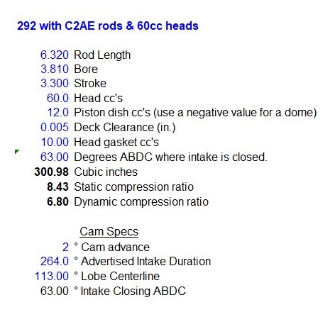
Ted thank you for sharing, I'll be sure to thoroughly verify all the journals and the c/c on the rods. I was finally able to find a good link for calculating static/dynamic compression ratios and was able to repeat the numbers you had posted. This brings me to another question in regard to piston domes/chamber volume and compression. It seems to be commonly stated that for a pump gas engine the dynamic compression ratio is best kept around 8:1-8.5:1. Given the stats you provided while using a 60cc chamber, I calculated a 9.8:1 static and a 7.99:1 dynamic compression. Is it best practice to mill the heads for increased compression or would you recommend adding a dome to the pistons and leaving the chamber as is? When adding boost to an engine, does dynamic compression stay the same or does it too need to be adjusted/lowered to support the added pressure? I hope I'm asking this in a way that it makes sense. My calculations led me to the following:
301" 60cc chamber, 10cc gasket, zero deck ht, flat top piston, 10 psi
static 9.8:1
Dynamic 7.99:1
Effective: 11.75
|
|
By Ted - 3 Years Ago
|
If going with a custom piston, then the preferred choice for altering the compression ratio is to work that change into the piston with a deck height and/or dome/dish configuration. Cylinder head modifications can prove to be extensive depending upon if trying to open up the combustion chambers to reduce the compression ratio or milling to increase the compression ratio.
For a normally aspirated engine, 8.2:1 DCR is the recommended maximum but that 8.2:1 number does not leave any room or tolerance for premium grade fuel that is less than advertised. For that reason, it's typically best to target for 8.0:1 DCR to leave just enough latitude for gasoline that may be slightly less than 91 octane with an engine tuned for 91-93 octane fuel.
When adding boost to an engine, the compression ratio is being artificially increased so the DCR number must be decreased accordingly. My rule of thumb is to reduce a full point of compression for each half an atmosphere of boost. A full atmosphere of boost is 14.7 psi so half of that would be 7.4 psi so if going with 7-8 psi of boost, then lower the DCR a full compression point. Instead of using the 8.0-8.2 DCR value as used for a normally aspirated engine, target that DCR number for 7.0-7.2 DCR for 8 psi of boost. All these numbers are for readily available pump premium gasoline (91-93 octane) so if using additives or racing fuel, then a higher compression ratio would be sustainable.
|
|
By Ted - 3 Years Ago
|
If going with 10 psi boost, then that calculates to be a 68% increase in atmospheric pressure. The compression ratio would need to decrease approximately 1.36:1 compression points in order to compensate. For the changed values you posted above, the new calculation would look something like this.
|
|
By 55blacktie - 3 Years Ago
|
|
I'm assuming those 60cc heads are Mummert aluminum heads. If that's so, will the DCR be lower than with iron heads?
|
|
By Ted - 3 Years Ago
|
|
55blacktie (2/12/2022)
I'm assuming those 60cc heads are Mummert aluminum heads. If that's so, will the DCR be lower than with iron heads?
Unless you change the camshaft and/or the connecting rod length, the DCR will ramp up and down at the same rate as the SCR ramps up and down when changing pistons or heads. If going with a larger chambered head on the above combination, then both the SCR and DCR will be lower.
|
|
By Ted - 3 Years Ago
|
|
55blacktie (2/12/2022)
I'm assuming those 60cc heads are Mummert aluminum heads. If that's so, will the DCR be lower than with iron heads?
In rereading your question again, I’m thinking maybe you are asking if the DCR requirements are different for the aluminum heads versus the iron heads?
If that’s what you are asking, then for the Ford Y I use the 8.2:1 DCR as a maximum number for the aluminum heads and 91-93 octane gasoline. In theory, the aluminum heads can get away with a more compression ratio than the iron heads simply due to the aluminum not retaining the heat so if that’s what you are asking, then the maximum DCR number for iron heads and 91-93 octane gasoline would be slightly lower than what you would see for aluminum heads. For the time being, we’ll call that number 8.0:1 for the Ford Y using iron heads and pump premium without any definitive testing and/or results to back that up. I typically do not have an issue with the DCR number for iron heads mainly due to the compression ratio on most iron head combinations being less than optimum simply due to the heads being too large to begin with.
|
|
By Ted - 3 Years Ago
|
Another point to consider when custom ordering pistons are the wrist pin locks. The Ford Y had full floating wrist pins as delivered from the factory and as such, required wrist pin locks. The FE and MEL engines also used full floating wrist pins. The SBF (289/302/351W,C,M) and 385 series engines (429/460) used a press fit on the rods for the wrist pins and did not require locks on the OEM pistons. Full floating is recommended in performance applications as any friction in the wrist pin area is distributed to additional points thus reducing overall friction.
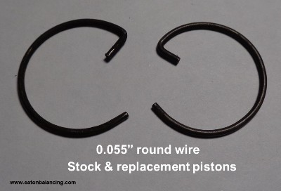
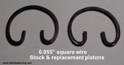
Many of the factory wrist pin retaining clips for the Y were round wire. The replacement cast pistons would have either round wire or square wire clips. Keep in mind that whatever wrist pin locking clip the pistons are machined for is the clip or lock that must be used as they are not interchangeable. The grooves within the wrist pin holes are specific to the lock that’s being used. With any locks that have an opening such as most round, square wire, and Tru-Arc locks, then install those with the opening vertical to the piston movement.
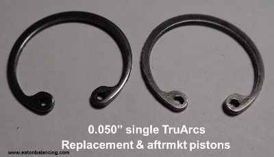
The aftermarket pistons use a variety of designs for the wrist pin retaining clips for the full floated pistons. They range from Tru-Arcs, single Spirolox (aka Spiro Locks), double Spirolox, and round wire clips. The Spirolox clips are typically easy to install but can at times be a challenge to remove.
Tru-Arc locks do require a good pair of lock ring pliers in which to install/remove these locks. With the Tru-Arc locks, you’ll find a sharp outer edge and a rounded edge on the other side. Install these with the sharp edge facing to the outside of the piston.
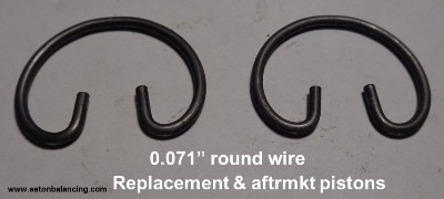
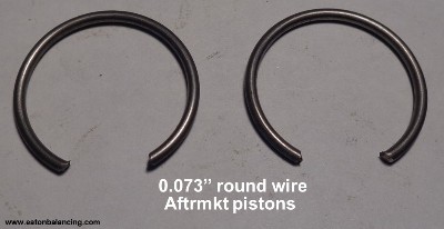
The 0.063” and larger round wire clips are much heavier in design than what Ford originally used in the Ford Y and while they can be hard on the thumbs when installing, they are relatively easy to remove as long as the piston has the notch in the wrist pin groove to allow a small pick or screwdriver to catch the underside of the round wire lock and simply pry it out. With these larger diameter round wire clips, it’s recommended that the wrist pin ends be chamfered on their outside edge to help keep the locks securely seated in their grooves.
With all that being said, my own preference is the 0.073” round wire clips when I have a choice as I have the specific tools to aid with their installation. Those tools beat a lot of wear and tear on the thumbs when installing.
When ordering custom pistons, just ask as to what the wrist pin lock options are as not all piston manufacturers offer the same options.
Here are pics representing just a sample of the various wrist pin retaining clips that are available.
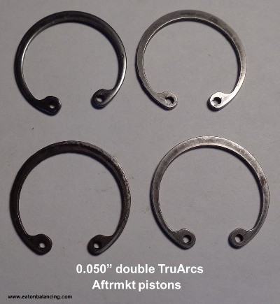 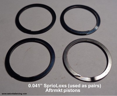
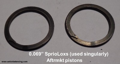 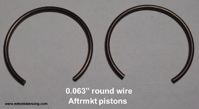
|
|
By NoShortcuts - 3 Years Ago
|
Ted and all. What a read this has been! OH! and GOSH! as a hobbyist, what I didn't know!
Thank You! 
Regards,
Charlie Brown
|
|
By Ted - 3 Years Ago
|
Wrist pin offset is yet another consideration when making custom pistons. For the majority of custom pistons, the wrist pins are merely centered which makes the pistons suitable for use in either the left or right banks of the engine. Many OEM pistons are designed with an offset wrist pin. A factory ‘ECZ’ 312 piston I have sitting here has an offset of ~0.060”. The original pistons get around the need for specific left and right bank pistons by marking a front on them thus allowing the pistons to have the offset in the right position in relation to the major and minor thrust sides of the pistons. When you see the four valve reliefs in a piston, it is so that piston can be flipped either direction to ensure that the wrist pin offset can be in the right place in relation to crankshaft rotation. Most oem and replacement pistons simply have a notch at their tops designating front but some of the aftermarket replacement pistons will be stamped ‘F’ or ‘Front’.
Why consider offsetting the pistons? By offsetting the wrist pin and when the piston is at either TDC or BDC, the rod is a slight angle to the piston bore and is positioned such that the piston will move or reverse directions with less resistance. In the centered wrist pin option, the rod is perpendicular to the stroke at both TDC and BDC and creates an additional amount of resistance for the connecting rod / piston combination to reverse direction. Having the offset wrist pins also makes for less piston slap (related to noise) when the piston is changing directions and thus a quieter engine.
If doing offset wrist pins in a custom piston, care must be taken to ensure that the pistons are installed in the left and right banks based upon the direction of the offset. If the piston is a plain flattop, then the piston is simply marked to indicate the front of the piston. On the other hand, if the piston only has two valve reliefs, has a combustion chamber specific dish, or has a dome, then the pistons will be marked accordingly so that the pistons are installed specifically in the left and right banks.
And this brings up another nuance as seen on the Flathead Ford V8 engines. Rather than offset the wrist pins in the pistons on those engines, Henry moved the crankshaft laterally to one side of the block thus allowing the crankshaft to be offset in relation to the centerline of the engine. This accomplished the same effect as using offset wrist pins. Just another way to have the connecting rods at a slight angle when the engine is at TDC and BDC.
|
|
By FORD DEARBORN - 3 Years Ago
|
|
Very good information, much appreciated - thanks.
|
|
By Ted - 3 Years Ago
|
Having received a couple of phone calls regarding how to calculate the wrist pin location in a custom piston, I’ll revisit this in slightly more detail.
Besides knowing the wrist pin diameter to be used, you will need to specify where the wrist pin centerline will be as measured from the top of the piston. In piston manufacturing terminology, this is referred to the compression height (CH). The factory wrist pin diameter for the Ford Y is the same as the later produced small block Ford engines (SBF) which is 0.912”. If using aftermarket rods or retrofitting connecting rods from another engine family, then the wrist pin needs to be compatible with those rods. While the factory sized 0.912” pins work well with the factory connecting rods, both the 0.927” and 0.866” pins are popular choices when aftermarket rods are being used. Regardless of the pin diameter that is chosen, it must match the wrist pin size of the connecting rod being used. While the CH value calculation does not take into account the actual wrist pin diameter, the wrist pin diameter is a consideration in that it is a player in determining the amount of room that is available between the top of the wrist pin and the piston top in regards to piston ring placement. If going with a larger diameter wrist pin, then that area is going to decrease and in some cases, may be a tight fit for the ring package.
The calculation for the CH is as follows.
Deck height minus connecting rod length minus half of the crankshaft stroke. This is for a zero deck combination. If wanting to have the pistons down in the hole a given amount, then also subtract the amount that the pistons are going to be below the decks. Here’s an example of the numbers for a zero deck Y-Block combination assuming the decks are being machined for a 9.750” deck height.
9.750” – 6.125” – (3.600” / 2) = 1.825” CH
If wanting the pistons 0.005” in the hole with a 9.750” deck, then the numbers look like this.
9.750” – 6.125” – (3.600” / 2) – 0.005” = 1.820” CH
|
|
By Ted - 2 Years Ago
|
|
If ordering the pistons with offset wrist pins, then make sure that the pistons are marked accordingly when you receive them. I recently received a set of pistons with offset wrist pins that were not marked indicating top, front, etc. Because I did catch this, it was a simple matter of looking at the wrist pin offset and marking the pistons with a Sharpie so that the rods could be installed correctly on the pistons.
|
|