Profile Picture

Electric Power Steering 56 Fairlane

Posted By kevink1955 9 Years Ago
You don't have permission to rate!
1
...
3
4
5
6
7
...
8

Author
Message
andrewb70
Posted 6 Years Ago
View Quick Profile
Turbocharged

Turbocharged (62 reputation)Turbocharged (62 reputation)Turbocharged (62 reputation)Turbocharged (62 reputation)Turbocharged (62 reputation)Turbocharged (62 reputation)Turbocharged (62 reputation)Turbocharged (62 reputation)Turbocharged (62 reputation)

Group: Forum Members
Last Active: 5 Years Ago
Posts: 31, Visits: 8.0K
I've been doing more research and found this link very helpful:

https://www.autoserviceprofessional.com/article/92544/Electronic-power-steering?Page=3

It seems that there is a "torque sensor zero point calibration" procedure for the Toyota steering ECUs. This is done by hooking up a Denso "intelligent tester" to the diagnostic port. We obviously can't do that very easily...but this seems important. 

I have not noticed any difference in steering effort when turning left or right. 

Andrew
kevink1955
Posted 6 Years Ago
View Quick Profile
Supercharged

Supercharged (426 reputation)Supercharged (426 reputation)Supercharged (426 reputation)Supercharged (426 reputation)Supercharged (426 reputation)Supercharged (426 reputation)Supercharged (426 reputation)Supercharged (426 reputation)Supercharged (426 reputation)

Group: Forum Members
Last Active: Last Year
Posts: 236, Visits: 237.6K
Andrew

I just cannot wrap my head around Holleys text on the speedo signal (sometimes I have nights like that)  It looks like they are producing a 12V + Square wave
All the testing I have done I was inputting a ground pulse to the ECU. I was going to attempt some bench tests tonight but it appears I only have 2 Pruis ECU's to play with on the bench. The Yarus non ABS is installed in the car (swore I had 2 of them)

I am going to look around and see if I can find the Yarrus ECU I thought I have, I can then test with both positive and negative pulses as my signal generator has outputs for both.

The only way I can see Holleys 12+ square wave working is if in it's off state it is pulled to ground, and in it's on state it's driven to 12V+.  It's not a normal square wave but they may have done it for compatibly reasons.  If thats the case you would never want to tie 2 outputs together as 1 could be in a ground state and the other in a + state, a dead short in my eyes.

The Yarus VSS pin when left unconnected is pulled to + (probability by a pull up resistor in the ECU) and the external device (my LED or Speedo VSS) pulls it to ground to initiate the pulse then releases the ground and it floats back up to +. Unfortunately my knowledge of TTL logic is from the electronics industry, automakers have always had a different way of doing things.

It took a long time to get used to grounding a relay coil to turn it on.  I imagine your fuel injectors are switched by ground and the 12V + is always supplyed.

I did see that site about the centering procedure but without the Toyota cluster there is no way we can do it, I have not had any steering effort balance problems and hope not to.

I am going to look around for that other ECU and if I find it I will do some tests to refresh my memory and will post the results

Kevin
andrewb70
Posted 6 Years Ago
View Quick Profile
Turbocharged

Turbocharged (62 reputation)Turbocharged (62 reputation)Turbocharged (62 reputation)Turbocharged (62 reputation)Turbocharged (62 reputation)Turbocharged (62 reputation)Turbocharged (62 reputation)Turbocharged (62 reputation)Turbocharged (62 reputation)

Group: Forum Members
Last Active: 5 Years Ago
Posts: 31, Visits: 8.0K
Kevin, 

We might be over thinking this. The Holley signal is definitely a positive square wave. I posted this before:
https://www.autozone.com/repairguides/Yaris-2007/Components-Systems/Vehicle-Speed-Sensor/_/P-0996b43f81b3d945#

From that link:


That is the wave form that is produced by the Toyota VSS and it appears to be a typical magnetic (VR...two wire sensor) sine wave. This signal is fed to the ECU. What we don't know is what sort of signal is being sent from the ECU to the steering computer. I suspect that it is a square wave, just like the Holley is putting out. 

The PWM+ signal is very similar. It is a square wave, going from 0 volts (off) to 12+ volta (on)...(I can also do a PWM- pulse, but I do not think that will work). I can adjust the frequency to anything that I want and also adjust the duty cycle. I think as long as the signal crosses the 0.5+v threshold shown in the image above, I am good to go.

The word I got from Holley is to use diodes on both signal wires, just to be safe. They also will never be ON at the same time. I plan to pulse the PWM+ signal for 5 seconds as soon as the ignition is turned on. My hope is that as soon as it sends the 5 second push, the Yaris ECU will come online. 

Andrew
charliemccraney
Posted 6 Years Ago
View Quick Profile
Supercharged

Supercharged (9.7K reputation)Supercharged (9.7K reputation)Supercharged (9.7K reputation)Supercharged (9.7K reputation)Supercharged (9.7K reputation)Supercharged (9.7K reputation)Supercharged (9.7K reputation)Supercharged (9.7K reputation)Supercharged (9.7K reputation)

Group: Moderators
Last Active: 3 minutes ago
Posts: 6.0K, Visits: 384.4K
I looked on Youtube.  On the surface, they jump a couple terminals and operate the ignition switch in a particular way to clear the old map, which causes a couple lights to flash as confirmation.  They then operate the switch in another way to set the new calibration, which causes lights to flash to confirm.

Any idea if that is strictly the EPS ECU or is more involved?  If it is only that ECU, then a pretty simple tool could be made using momentary switches and leds to set the calibration - you just need to know how they need to be connected.


Lawrenceville, GA
andrewb70
Posted 6 Years Ago
View Quick Profile
Turbocharged

Turbocharged (62 reputation)Turbocharged (62 reputation)Turbocharged (62 reputation)Turbocharged (62 reputation)Turbocharged (62 reputation)Turbocharged (62 reputation)Turbocharged (62 reputation)Turbocharged (62 reputation)Turbocharged (62 reputation)

Group: Forum Members
Last Active: 5 Years Ago
Posts: 31, Visits: 8.0K
charliemccraney (11/15/2018)
I looked on Youtube.  On the surface, they jump a couple terminals and operate the ignition switch in a particular way to clear the old map, which causes a couple lights to flash as confirmation.  They then operate the switch in another way to set the new calibration, which causes lights to flash to confirm.

Any idea if that is strictly the EPS ECU or is more involved?  If it is only that ECU, then a pretty simple tool could be made using momentary switches and leds to set the calibration - you just need to know how they need to be connected.


I am assuming you are talking about the torque sensor centering calibration...

The issue is that the steering computer is connected to the main ECU via CAN bus. The "intelligent tester" communicates with the main ECU and the steering computer gets its instruction from there, or at least that is how I understand it. 

I found this:
http://www.toymods.org.au/forums/threads/79652-Electric-power-steering/page2

Post #23 is very interesting. He was working on making the steering ECU power on, before moving, as well. He went down the rabbit hole of emulating the CAN signal to tell the steering ECU that the engine was running, which apparently worked.

Andrew
andrewb70
Posted 6 Years Ago
View Quick Profile
Turbocharged

Turbocharged (62 reputation)Turbocharged (62 reputation)Turbocharged (62 reputation)Turbocharged (62 reputation)Turbocharged (62 reputation)Turbocharged (62 reputation)Turbocharged (62 reputation)Turbocharged (62 reputation)Turbocharged (62 reputation)

Group: Forum Members
Last Active: 5 Years Ago
Posts: 31, Visits: 8.0K
Alright. Awesome news. I wanted to temporarily try the PWM+ trigger to turn on the steering ECU. I am able to configure the output on the Dominator all in software. So I simply reprogrammed the original speedometer output and created the PWM+ output and assigned it to the same pin as the speedometer output (the speedometer output had to be virtually unpinned from that location). Anyway...

I set the frequency to 1000Hz and a duty cycle of 50%, so half the pulse is on and half the pulse is off, very much like a speedometer signal. Turned the ignition off, turned the ignition back on, and immediately had power assist. The diodes will be here tomorrow so I will add the second wire to the steering ECU speedometer input. The result should be having immediate PS as soon as the ignition is turned on and there after, it will receive the speedometer signal and operate by changing the level of assist based on speed.

Andrew
andrewb70
Posted 6 Years Ago
View Quick Profile
Turbocharged

Turbocharged (62 reputation)Turbocharged (62 reputation)Turbocharged (62 reputation)Turbocharged (62 reputation)Turbocharged (62 reputation)Turbocharged (62 reputation)Turbocharged (62 reputation)Turbocharged (62 reputation)Turbocharged (62 reputation)

Group: Forum Members
Last Active: 5 Years Ago
Posts: 31, Visits: 8.0K
Kevin,

Have you played around with any of the other pins to see if the ECU will turn on prior to receiving the speed signal?
Have a look at this:


I am wondering if sending a pulse to pin 2 will wake it up. Any chance you can try this on the bench?

Andrew
kevink1955
Posted 6 Years Ago
View Quick Profile
Supercharged

Supercharged (426 reputation)Supercharged (426 reputation)Supercharged (426 reputation)Supercharged (426 reputation)Supercharged (426 reputation)Supercharged (426 reputation)Supercharged (426 reputation)Supercharged (426 reputation)Supercharged (426 reputation)

Group: Forum Members
Last Active: Last Year
Posts: 236, Visits: 237.6K
Andrew


I wish I could bench test it but I think the only Yarus ECU I have is in the car, only thing I have on the bench is 2 Prius units but we already know they turn on in failsafe without anything else. I swore I had another Yarus ECU but I cannot find it.

It looks to me that pin 2 is an output to confirm the setup tool has connected via Can Bus to the ECU. the wave form shown is an output so you could not (I think) drive  it externally.

Have you done anymore driving with the speed sensing working?   Looking for info on how the steering feels compared to the fail safe mode.

andrewb70
Posted 6 Years Ago
View Quick Profile
Turbocharged

Turbocharged (62 reputation)Turbocharged (62 reputation)Turbocharged (62 reputation)Turbocharged (62 reputation)Turbocharged (62 reputation)Turbocharged (62 reputation)Turbocharged (62 reputation)Turbocharged (62 reputation)Turbocharged (62 reputation)

Group: Forum Members
Last Active: 5 Years Ago
Posts: 31, Visits: 8.0K
[b]kevink1955 (11/17/2018)
.....
Have you done anymore driving with the speed sensing working?   Looking for info on how the steering feels compared to the fail safe mode.


Yes, I have done quite a bit of city and a little highway driving. It feels like a completely different system than what it felt like in "fail-safe" mode. I have to admit, I was a little disappointed on the first drive in "fail-safe" mode. If I am not mistaken "fail-safe" mode is the middle level of assist and damping. So when going slow the steering felt under powered and when driving on the highway it felt over boosted.

Driving now is really great. The steering is light when going slow. I love being able to make parking lot maneuvers with one hand. This was impossible with the manual system. Driving around town is also great. I think (I don't have an easy way to confirm this) the middle level of assist kicks in around 35 mph. So city driving is mostly at this level of assist. The steering is feels firmer and more dampened. On the highway it's very nice too.

The biggest impact to the whole swap, in addition to much easier parking, is the added damping. My TCP rack has zero damping. The TCP racks are made by Woodward and they are serious racing units. They are designed to transmit a lot of road feel to the driver. While this is great for a race car, it's not so great for a street car. Even modern performance cars have to balance this with their steering systems. I will give you an example of how sensitive and intense the feed back was through the steering wheel. For instance, when I used to go over a particular set of railroad tracks, I would literally take my hands off the steering wheel. I did this because as the car went over the rough crossing, you could feel every bump through the steering wheel. I am sure some of it is bump steer, but a lot of it was simply the small movements of the rack being transmitted to the steering wheel. When I drive over the same tracks now, there is literally nothing that is felt in the steering wheel. It just glides over bumps, like you would expect any modern car to do. The same goes for when going over any bumps, nothing is felt in the wheel. 

My biggest complaint is still the lack on on-center feel and having that razor crisp return to center that I had before. However, I feel that this is a small price to pay considering all of the other benefits. The on-center feel is much better on the highway in speed sensitive mode than it was in "fail-safe" mode. 

Andrew

andrewb70
Posted 6 Years Ago
View Quick Profile
Turbocharged

Turbocharged (62 reputation)Turbocharged (62 reputation)Turbocharged (62 reputation)Turbocharged (62 reputation)Turbocharged (62 reputation)Turbocharged (62 reputation)Turbocharged (62 reputation)Turbocharged (62 reputation)Turbocharged (62 reputation)

Group: Forum Members
Last Active: 5 Years Ago
Posts: 31, Visits: 8.0K
The plot thickens....

I have been digging deeper into the ins and outs of the Toyota EPAS system. One thing that I ran across is that the Toyota systems have a "torque sensor zero point calibration" that must be performed in case of a wheel re-alignment or if the motor assembly is replaced. This is described well here (toward the bottom of the page):

https://www.autoserviceprofessional.com/article/92544/Electronic-power-steering?Page=3

As far as I have seen, nobody has talked about this when installing the Toyota gear into older vehicles. This seems like a very important procedure and the fact that nobody is doing it, leads me to believe that it is partially (if not fully) to blame for the lack of centering that I (and others) are experiencing with the system.

Another thing that I found out, and this is a bit confusing, is that apparently, the Yaris ECU doesn't actually go into full speed assist mode unless it sees an RPM signal come across the CAN bus. This is confusing to me because I swear that my system does change the level of assist based on speed, but I have no concrete way to verify this, except for how it "feels" to drive. This has also been tested by others on the bench (Kevin) by connecting a square wave generator to the Yaris ECU speed input (pin 5) and reporting variability in assist level based on altering the pulsing frequency.

The information found here is invaluable (post #23):
http://www.toymods.org.au/forums/threads/79652-Electric-power-steering/page2

I have been in email contact with the original poster (his name is Jared) of that thread. Here is a more complete pin-out for the Yaris steering ECU:


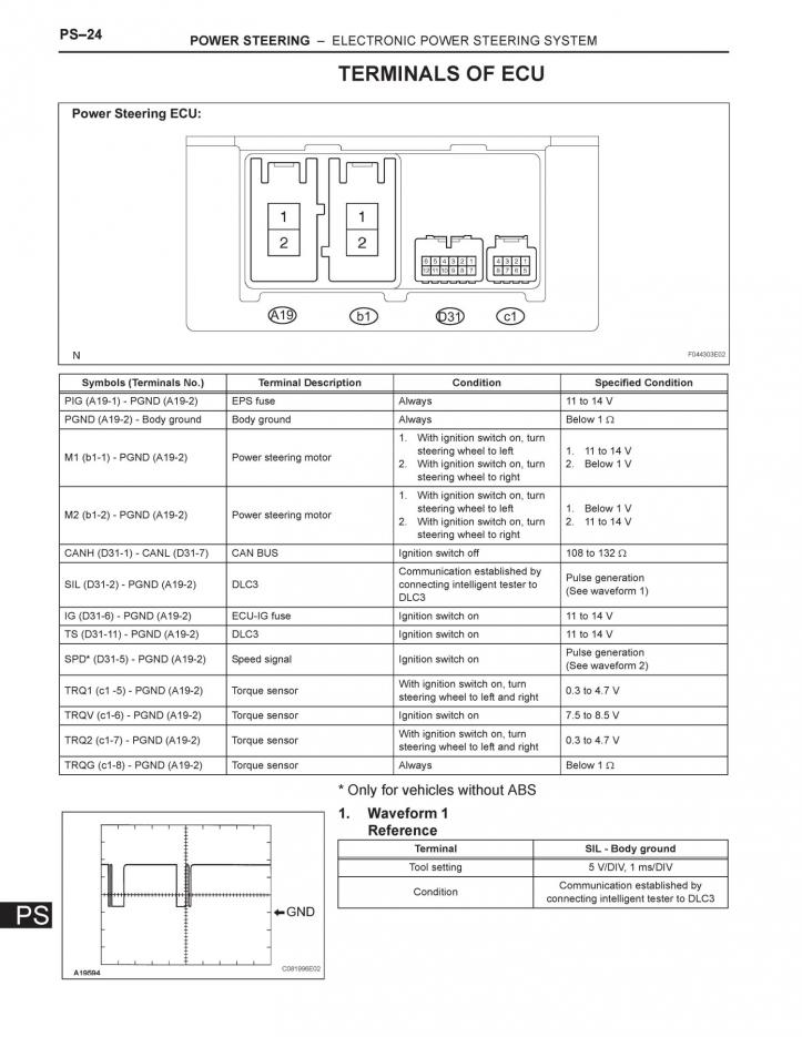
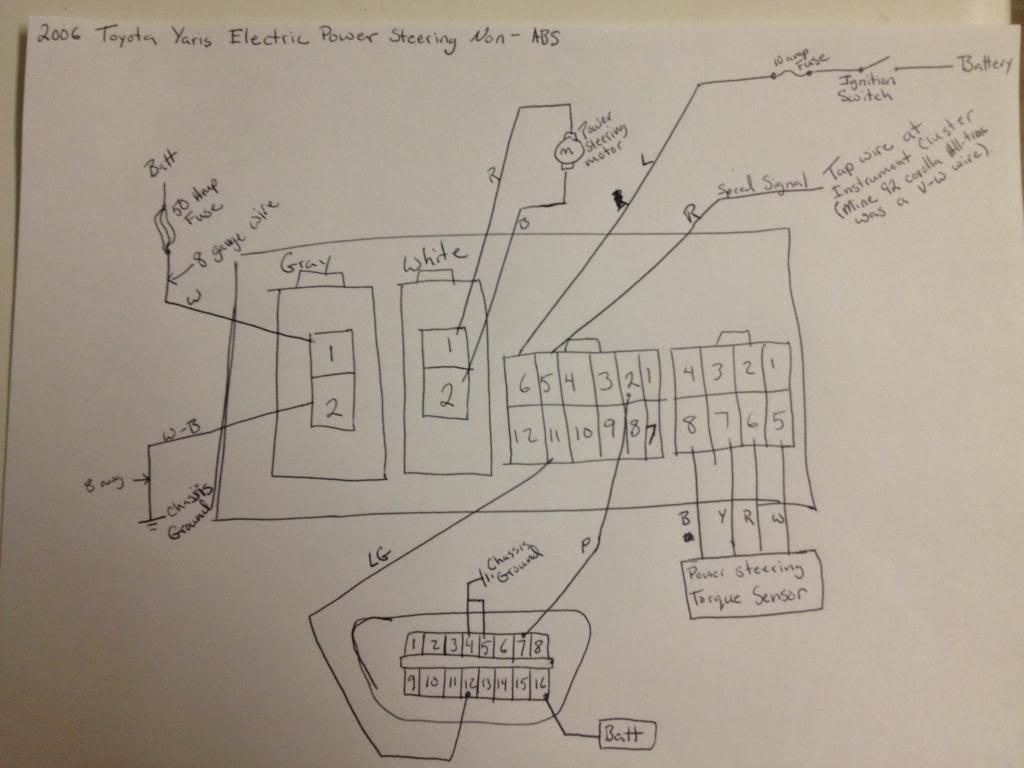
This is a wiring diagram that Jared put together.


Jared solved the CAN signal issue by using and custom programming the CANdo Auto Module:
http://www.cananalyser.co.uk/candoauto.html

Here is an excerpt from his post on the Toyota forum:

"I going to jump into technical which will make much more sense once you research the CAN system. I was able to find the hex decimal code for engine RPM is 2C4 wheel speed is either 0B0 or 0B2. Since my setup has a non ABS eps ecu has an analog wheel speed signal (input). I only needed the engine RPM on the CAN network so i will only go over how I programed the Cando for this. The Cando has 2 analog inputs that can be programed to then transmit programable CAN data. It also can have ten static data points programed and continually repeated. When you get the software open there are four tabs. "Input view", "Input setup", "CAN transmit" and "CAN setup" first off we need to go to "CAN setup" and change the setting to 500kps to match the network speed of the CAN system. Then back to the tab "CAN transmit". Now as I said earlier the hex for RPM is 2C4. The data length is 11 bit. The dlc is 8. The information I used was ramdomly picked after much trial and error. Almost 3 pages of codes I tried. I could set the RPM in connect my scan tool and see the RPM but still no assist. After much frustration I finally realised that it was a setting I had wrong. It was how often I had it repetting the message. The end result looked something like this 2C4 8 06 8A 00 19 00 00 92 09 Repeat rate 20 ms(milliseconds). All this done and turned the car on and immediate assist. I still have not been able to drive the car and see if it feels bettter. Still working on some idle issues with the engine. I could however tell the assist was greater. Last thing to work on is connecting the CAN wiring to the DLC so i can see about changing the setting for the assist level at idle."

What makes this more frustrating for me is that the Holley Dominator does use CAN communication. This is used for communication with Racepak and the Holley digital displays. The frustrating part is that the Holley CAN protocol is proprietary, so the odds of the Yaris steering computer "understanding" the Holley data packets are nil.

Before I go down the same path as Jared, I need to have a conversation with DCE. Their Microsteer ECU is speed sensitive. The only question remains is if the Microsteer ECU is compatible with the Toyota motor. If it is compatible, then I am inclined to ditch the Toyota ECU and simplify this ordeal by spending money on the Microsteer ECU instead of buying the CANdo box. I also need to find out how DCE handles the torque sensor center point calibration, as this seems rather important for obtaining satisfactory on-center feel and return.

I am open to thoughts and suggestions!!!


1
...
3
4
5
6
7
...
8


Reading This Topic


Site Meter