|
By kevink1955 - 11 Years Ago
|
I screwed up Photo posting so badly last time so I hope I do better this time
I have installed Electric power steering From an 08 Totyota Yarus in my 56 Fairlane. The Yaris unit is column mounted and drives the steering box worm shaft based on the amount of torque you put on the steering wheel. I will say it has plenty of power as I was tuning the wheel lock to lock with 1 strong finger while sitting on a concrete floor on underinflated radials. (I have the black marks on the concrete and flat spots to prove it LOL)
I finally got to take the car for a ride now that the roads are free of slush and salt, I almost lost it on my first turn out of the driveway as I am used to grabing the wheel with both hands for the tight turn. Lets just say the wheel can now be palm steered, it returns to center just like it always did, I like it so far but only drove about 10 miles as the roads are not completely clear and my inspection is expired.
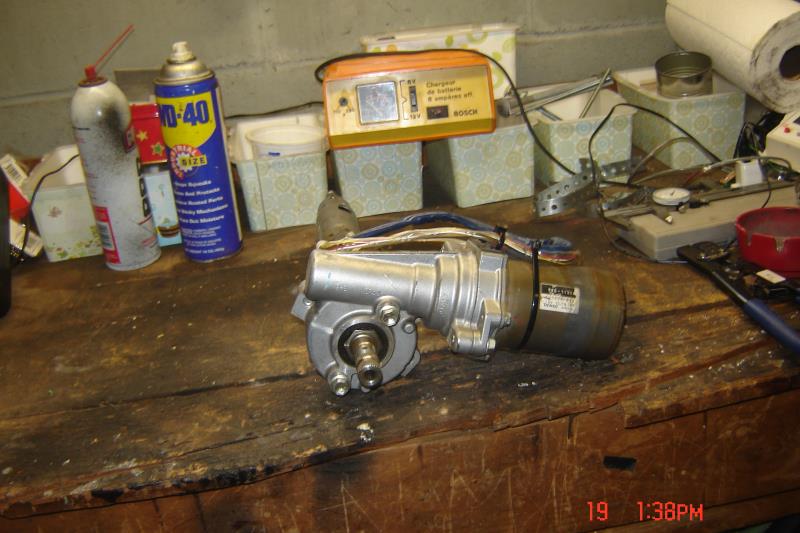
I am going to try 1 picture first and see how it goes, the pic is of the Yaris EPS unit, Will follow up with what I did to install it. The end you are looking at is the output end
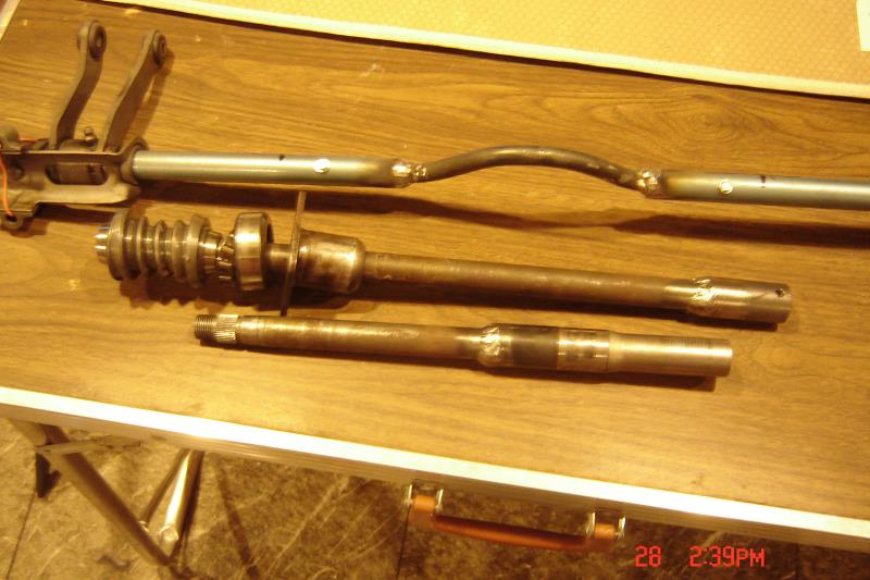
Next is a Photo Of the modified Shifter shaft, 56 Worm shaft shortened with spline coupler to mate with the Yaris Output and the upper shaft with spline coupler to mate with the Yaris input
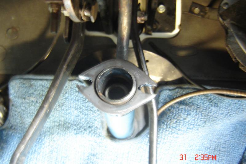
Next is the lower Column tube with a flange welded on the end to mount the Yaris unit, note the worm shaft with coupler inside the tube.
Next is the unit bolted up to the flange and coupled to the upper column tube
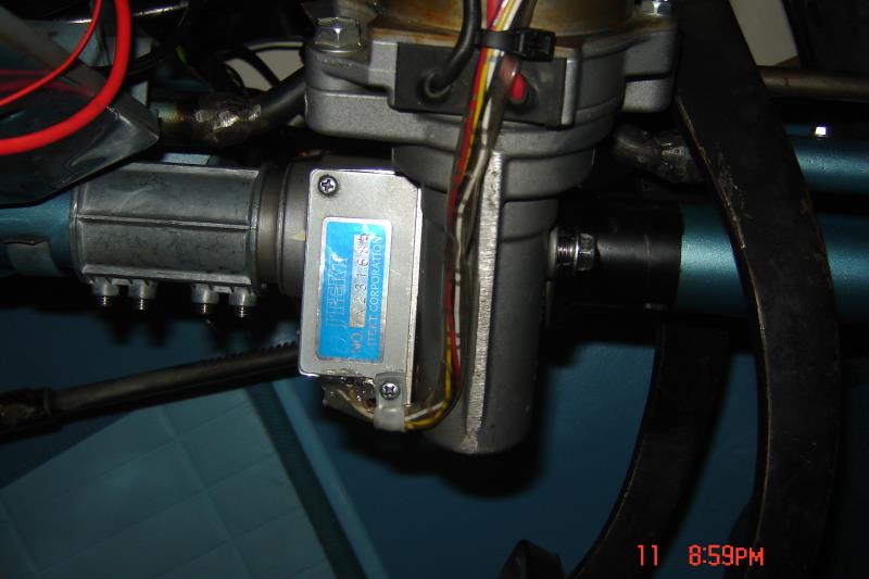
Next is what it looks like looking thru the wheel
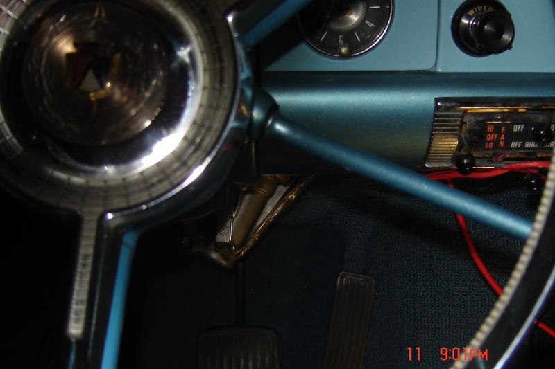
And a view looking up under the Dash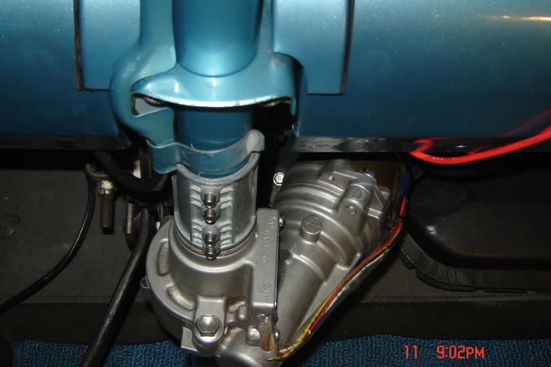
I have it running in full power mode right now but with the proper Vehicle Speed Sensor it could be made Speed sensitive, less boost at highway speed, more at low speed. At this time I am putting together a list of what Yaris units will work, the unit requires an Electronic Control Unit (ECU) and as far as I can find out so far the ECU has to be 2007 thru 2009 Yaris without ABS. The motor is a little less critical 2005 thru 2011 Yaris and Prius work
|
|
By kevink1955 - 11 Years Ago
|
By the way this was not my idea I got it from Vintage Mustang Forum, A user there named SlowPoke started this thread, look at the link below
http://forums.vintage-mustang.com/mod-custom-forum/787114-best-200-mod-ever-eps.html
They are using a unit from the Saturn Vue, that unit would not work in my 56 as the housing had clearance problems with my Clutch Linkage, the motor would have had to be on the left side. The Totoya units have the housing reversed so I could clock it up and to the right, My user name over there is sons67, go have a look. A month ago I knew nothing about Electric Power Steering, 1 month later it's installed and working in my Fairlane, Thanks Slowpoke and VMF!1
|
|
By lowrider - 11 Years Ago
|
|
Looks good. The reason they need a ECU & other sensors in the system is to give the unit a "road feel" while your driving it. It will feel over sensitive or steer like a boat without it. Ford came out with that type system on some cars before I retired. Their's was a "drive by wire" system. No column shaft going into the unit, just a sensor in the column that told the ECU how much to turn the wheels. Looked pretty strange under the dash without a steering shaft running through the firewall.
|
|
By slick56 - 11 Years Ago
|
This bloke here has fitted a unit to his Cobra,
https://www.youtube.com/watch?v=bH5a1iUrXvo
and he has a variable controller available on eBay, instead of an ecu
http://www.ebay.com/itm/Saturn-Vue-Ion-scrubrolet-Equinox-Electric-power-steering-controller-box-EPAS-/171027023129?hash=item27d2014519&vxp=mtr
Great idea...
.
|
|
By Lord Gaga - 11 Years Ago
|
I know some of us are thinking, why bother ? So the "little woman" can drive the car ? 
Toyoga parts on a Ford is worse than chivy parts !
Banzai !
|
|
By kevink1955 - 11 Years Ago
|
LowRider, I have the Yaris ECU and it has an input for a Vehicle Speed Sensor, All I need is a sutiable VSS that I can put in the speedometer cable to generate the pulses. I have bench tested the unit with the ECU on the bench using a Square wave generator and find the ECU has 3 levels of assist.
At 5 pulses per second it has full assist, at around 45 PPS it changes to a lower assist and mildly dampens rapid movments, at around 75 PPS it changes to a very mild assist and greatly dampens rapid movments.
The damping goes away of you jerk the wheel as in an emergency lane change.
Lord Gaga, I am 1 to agree that you should keep your Ford all Ford, where everyone else is using GM alternators I stuck with Ford but in this case Ford does not apear to have anything that will fit or operate on only VSS input so Totoya it is. I would like to drive and enjoy this car and considered installing original PS but the price of good/rebuilt units is way out of my price range. I also looked at Borgenson but with 3 on the tree you would have to shorten the column so much that the shift linkage arms would be inside the car.
|
|
By '60 Fairlane - 11 Years Ago
|
|
Kevink1955, this is interesting. Let me make sure I'm understanding. You still have your OE box and the Yarus piece is sandwiched, or spliced, into the OE column. Correct? And, you kept the three on the tree shifter. Very interesting. Thank you, -Dave.
|
|
By kevink1955 - 11 Years Ago
|
Yes, that's it just cut out a section of the original steering box shaft and column and weld in some spline adapters. The shift rod is cut and a 1/2" steel rod is bent to hop over the steering motor gear box. It worked out fine, no changes in the way it shifts, infact it shifts better with all the old hardened grease cleaned out.
You will require an ECU from a Yaris without ABS and a way to fool the VSS input into thinking the car is moving.
I used a flashing LED (the fake alarm type) between the VSS input and ground, the pulse every time the LED blinks generates a Square Wave to the VSS.
Someone mentioned the Saturn unit and ECU witha box with a Pot from E-Bay, while that seems to work for the Mustangs it will not clear the clutch linkage (pedal stop) without having the motor hanging out under the dash and I think in that position the emergency brake would have to be moved also. The Yaris unit has the worm gear slung on the other side so it clears every thing but the shift rod,
As I understand the E-Bay box it is providing GM bus (2 wire digital addressed signal) to fool the GM ECU into thinking the Cars ECU and ABS modules are sending it commands that are adjustable by the Pot, I like the Yaris 1 pin square wave as it can be created easier
|
|
By '60 Fairlane - 11 Years Ago
|
|
Kevink1955, I followed your link to the vintage.Mustang thread. Interesting indeed, I would never even thought of such a swap/upgrade. One more question. Is there a "fail safe", if the motor should fail can the vehicle still be steered? Thanks, -Dave
|
|
By kevink1955 - 11 Years Ago
|
|
Yes it can still be steered if the unit fails you would just be turning the motor as well as the steering shaft. The unpowered motor takes very little effort to turn, during my testing of the unit on the bench, the weight of an 8" Vice grip on the shaft would rotate it.
Now if the electronics failed and commanded the motor right when you wanted to go left it would be a fight I do not know who would win. Hopefully the engineers who designed the ECU built in a fail safe for that!!
Ever reverse the ram hoses on a ford power steering, scary
|
|
By waid302 - 10 Years Ago
|
Hello Kevin
My name is Waid. I was the guy that originally posted the Saturn Electric Steer when I discovered the guy in Europe and posted the $100 Electric Steering topics.
I am curious about the Yaris Electric Steer. It appears that you not using the module from the guy on internet.
When say ECU, are you talking about the electric steering controller or the car computer ?
How did you wire it?
http://www.fordmuscleforums.com/all-ford-techboard/538585-100-power-steering-yes-you-can-use-column-electric-power-assist-system-epas.html
http://www.fordmuscleforums.com/all-ford-techboard/538585-100-power-steering-yes-you-can-use-column-electric-power-assist-system-epas.html
|
|
By kevink1955 - 10 Years Ago
|
By ECU I am referring to the Yarus steering control module from a non ABS brake equipped 2007-2009 Yarus, it has to be non ABS as it relies only on the Vehicle speed sensor (VSS) and does not use CanBus so no internet controller is required.
Wiring is simple, Direct 12V from battery (about 50 amps max only when providing assist)
Switched 12V ignition to turn the unit on and off (less than 1/2 amp)
A pulsed to ground VSS signal to turn the unit on and control the level of assist
I still have not installed a VSS and am using a flashing LED (the fake alarm indicator kind) to provide the 5 PPS to turn it on
I still want to install the speedometer driven VSS I have but have not have the time, without the VSS varying the assist it feels just like the original 56 power steering, very light and over boosted. It would be nice to reduce the boost at high speed and I will get around to it some day
So far I like it and due to some recent health problems it enables me to drive and enjoy the car instead of looking at parked in the garage.
Since the high current draw only occurs when providing high levels of assist no upgrade to the charging system is required. going straight and in minor corrections at speed it draws nothing.
|
|
By waid302 - 10 Years Ago
|
Kevin,
What is the part number on the Yaris Non-ABS ECU ?
Thanks
|
|
By kevink1955 - 10 Years Ago
|
I have tested both these Yaris ECU's and they work fine. I also found a Prius ECU that will turn on after 10 seconds if it has no communication from the vehicle ECU. Guess this is a fail safe to allow power steering when the vehicle is being pushed or coasting to the side of the road if the engine dies.
ECU 89650-350 08 Yaris* Works in VSS Pulse
Jtekt 991-39900
112900-2200
EPS 12V Denso
Toyota parts zone says 07-09 yaris 89650-360 is the replacement for this unit
OEM Parter says 89650-360 is the replacement for this unit
ECU 89650-140 08 Yaris* Works in VSS Pulse
Favess 991-28701
112900-1062
EPS 12V Denso
Toyota parts zone says 07-09 yaris this is a current part #
OEM Parter says this is a current part #
|
|
By famdoc3 - 10 Years Ago
|
|
A square wave generator is easy. I built one to run my electronic speedometer in my streetrod. I used a g.m. Speed sensor from a 90s 4l60e transmission. I then made an aluminum disc about 5 inches in diameter and mounted a number of disc magnets in it. I then bored it to fit on the driveshaft and presto a square wave generator!
|
|
By kevink1955 - 10 Years Ago
|
|
I already have a VSS that I can splice into the speedometer cable (may need an adapter on 1 side). I have already run the VSS with a cordless drill and it will do what I need. Just need to get my sore butt under the dash to get it done, looks like a winter project
|
|
By waid302 - 10 Years Ago
|
Kevin,
I have the wiring diagram for the Prius and also the Yaris both Prius and Yaris are connected to the can bus.
Yaris steering ECU uses the VSS signal which is fed by the speedometer for variable power assist.
Prius does not have a VSS signal input. Per the manual it will default to a preset power assist if the can bus is not connected. As you stated earlier the Prius electric steer will work after about 10 second delay because it is trying to communicate with the can bus.
I have bench tested the Prius EPS on default fail safe mode but not sure how much the power assist is until I put wheels on car and test it.
My question to you is since your Yaris steering ECU is also not connected to the can bus do you get instant power assist soon as you turn the ignition on or do you also have to wait about 10 seconds?
Waid
|
|
By kevink1955 - 10 Years Ago
|
Waid
The 2 Yarus ECU's I have tested will not provide any assist at all without can buss till the VSS input sees about 5 pulses at around a 5 PPS rate. I provide this pulse train using a flashing LED (the kind you buy to make it look like your car has an alarm system) The LED is wired Positive to the VSS pin and Negtive to Ground. Every time it blinks it pulls the VSS pin to ground, fooling the ECU VSS into sensing that the car is moving.
You are correct that the Prius ECU will turn on in a few seconds without can buss but it will always be at full power assist as it has no VSS input (the pin is there but has no voltage on it like the Yarus does. With the Yarus I can put a VSS driven by the speedometer and have variable assist, I intend to do that this winter.
At full assist the steering feels overboosted, not unlike the factory hydraulic system. I had a friend who has the factory system in his car drive mine and he did not feel any difference
|
|
By waid302 - 10 Years Ago
|
I got my hands on 07 Yaris steering column with ECU non-ABS ($36 ! ). I already had a pulse generator with flashing LED with variable duty cycle and I was able to actuate the ECU. The Yaris EPS is much smaller compared to Prius which is fine if you are using manual steering box. I used to be a steering engineer at Ford and I can tell you that the load rating for Yaris would be too small to be used with Rack & Pinion in a bigger car. I have converted a Cavalier Rack to manual for my Falcon. The good news is that the ECU for Yaris works with Prius EPS because both uses same torque sensor. The Yaris ECU works instantly as soon as it sees couple of pulses even if the pulse generator is removed afterwards.
According the Prius EPS troubleshooting guide, if the steering ECU sees CAN bus malfunction (like broken communication), Amount of power assist is fixed for a speed of 43 mph (70 km/h). I assume this means that what ever assist level that is provided when everything is working fine at 43 mph. Typically at 43 mph, there would be very little assist needed. Therefore, I am thinking that the steering assist will be very low when the car is not moving.
I did an un-scientific bench test with Yaris ECU (with flashing LED) and Prius ECU. I held the motor down by hand with the output shaft locked in vice with another person moving the input shaft with a vice grip pliers. Both the Yaris and Prius did not feel any different in terms of how much force I had to apply to hold the motor down.
I hope to test the entire system this weekend with both Yaris and Prius ECU.
|
|
By kevink1955 - 10 Years Ago
|
You are correct, the Prius unit has a larger gear case than the Yarus but they both have the same motors.
I did testing with both types a spring scale to see how much power they can output, I used the Yarus ECU for both tests and the output for both was almost the same. It may be that the ECU is what limits the power.
I will say that the Yarus motor and ECU will dry steer my 56 Fairlane with radials on dry concrete and that's plenty for me.
The testing I did with the Prius ECU felt like full power without can buss where your research says it is at the 43 MPH rate, wish I had time to play with it some more but not now, may try more mid winter.
Keep us informed of any thing else you find, we all learn from each other. I never would have thought of this if not for the Mustang forums and their GM steering projects
|
|
By waid302 - 10 Years Ago
|
kevink1955 (9/17/2016)
Keep us informed of any thing else you find, we all learn from each other. I never would have thought of this if not for the Mustang forums and their GM steering projects
I posted the Vue stuff 2 years ago on Mustang, Falcon and FMF and it took off like wild fire!
I had so much stuff to do on my Falcon, I did not bother with the EPS until now that I am ready for it. Personally, I am not too crazy about hooking up 3rd party box to the steering ECU. A lot of time in research and development went in to the system. I would rather have fail safe default mode for safety.
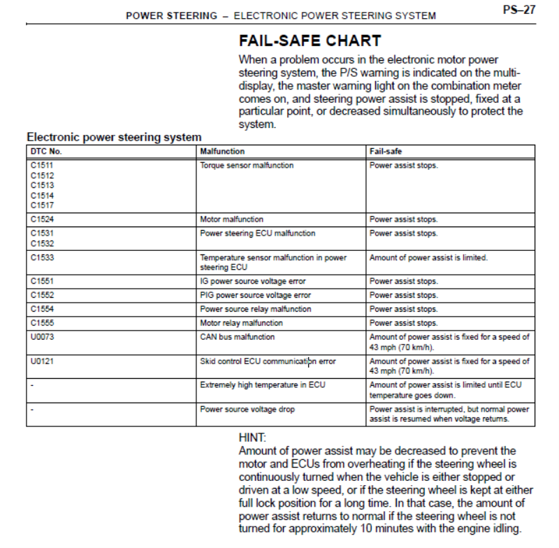
Below is the fail safe for Yaris as well. As you can see, it does not care about CAN BUS. If it does not see the engine ECU, the Amount of power assist is fixed for a speed of 43 mph (70 km/h). Therefore both the Yaris and Prius "feels" the same.
Kevin, you should not have any issue with steering returning back to center when you come out of a turn do you?
The Saturn Vue EPS has this issue with the eBay box.
Waid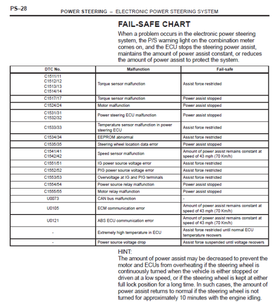
|
|
By andrewb70 - 8 Years Ago
|
I signed up to this forum, just because of this thread. Waid, thanks again for posting all of this information and making it available to the world. That is exactly what hotrodding is all about.
Kevink, I really appreciate the information that you posted regarding the activation points of the 3 levels of assist with the Yaris non-ABS ECU. I was originally thinking that the level of assist is directly related to speed in a linear fashion, but clearly, your experimentation with the flashing LEDs has demonstrated otherwise.
A little about myself, I have a 1967 Cougar, with an unfortunate engine swap, T56 trans, blah...blah...blah...
I have a TCP manual steering rack, and even with the skinny front tires, the steering effort is very high. The engine is managed by a Holley Dominator ECU. One of the things that the Dominator can do is generate a square wave pulse based on vehicle speed. I currently have the T56 VSS sensor wired to the Dominator and it registers and displays (through a Holley 7" dash) accurate speed. Obviously, what I am hoping to do at this point is output a signal from the Dominator to the Yaris ECU and have variable levels of steering assist based on speed. From what I have been able to gather from various information sources is that this should be doable.
Again, thank you to everyone for supplying various bits of information.
Andrew
|
|
By kevink1955 - 8 Years Ago
|
It should work provided the square wave being generated is the proper polarty.
The Yarus ECU VSS pin when unconnected is pulled positive and is looking for pulse's to ground from the VSS (or my LED)
As long as you can provide negative going pulses it should work fine.
Let us know of your progress on this as we are still learning this unit, I love how mine works, makes the car so much easier to drive and no messy fulit leaks
|
|
By andrewb70 - 8 Years Ago
|
kevink1955 (11/4/2018)
It should work provided the square wave being generated is the proper polarty. The Yarus ECU VSS pin when unconnected is pulled positive and is looking for pulse's to ground from the VSS (or my LED) As long as you can provide negative going pulses it should work fine. Let us know of your progress on this as we are still learning this unit, I love how mine works, makes the car so much easier to drive and no messy fulit leaks
Kevin,
Can you elaborate more on this please. Another option I have with the Dominator is creating a PWM output. This can be either PWM+ or PWM-. As I understand it, the PWM+ creates a positive square wave, while the PWM- creates a negative square wave pattern. I can configure this output with a table based on vehicle speed. In a previous post you mentioned a couple of critical values, those being 5, 45 and 75 pulses per second as being the threshold values for the three levels of assist.
As I understand it, 5-44 PPS results in high assist, 45-74 PPS results in a medium level of assist, and greater than 75 PPS gives the least amount of assist. The PWM table can be populated with pulse width values (in msec).
Judging from this article:
https://www.autozone.com/repairguides/Yaris-2007/Components-Systems/Vehicle-Speed-Sensor/_/P-0996b43f81b3d945
It looks like I should use a PWM+ output signal.
Thanks for the reply and I appreciate all the help!
Andrew
|
|
By kevink1955 - 8 Years Ago
|
Andrew
I am not sure about PWM signal, When I did my testing on the bench I was using a square wave generator and varing the frequency.
I also found an Analog sine wave would work it does not seem to be to critical.
Let us know how it works out
|
|
By andrewb70 - 8 Years Ago
|
kevink1955 (11/4/2018)
Andrew I am not sure about PWM signal, When I did my testing on the bench I was using a square wave generator and varing the frequency. I also found an Analog sine wave would work it does not seem to be to critical. Let us know how it works out
I will definitely keep you posted!
Andrew
|
|
By andrewb70 - 8 Years Ago
|
Hello everyone,
This afternoon I finished the Prius EPS install on my Cougar.

If anyone wants to see the full install, it can be found here:
https://www.pro-touring.com/threads/109464-1967-Cougar-build-(over-700-pictures-and-videos)/page61
Starts at post 1203.
I also installed the wiring from the Holley Dominator to the Toyota ECU. I have not done any testing with it yet, because I need to do some reconfiguring of wires at the ECU, but I should have results soon. I had a buddy of mine make a spread sheet that does the math to convert Kevin's 3 inflection points to pulses per mile (ppm). In the Dominator output I can enter any PPM number which I am hoping will allow me to change the speed at which the middle level of assist is triggered.
I welcome any thoughts and suggestions.
Andrew
|
|
By kevink1955 - 8 Years Ago
|
Andrew, looks good.
Carrying the column tube all the way thru the firewall is a good idea, the amount of torque produced by the steering motor is equal to what you used to input via the steering wheel via the Armstrong Steering (manual). Without proper support it could rip the motor right off the dash bracket.
Question, What ECU are you using that it is turning on without pulsing the VSS pin. All my tests on the Yarus Non ABS ecu needed pulses to turn on, once on it would continue to provide power assist. Varying the pulse rate would change the amount of assist provided.
The prius ECU (and I believe Yarus ABS) will turn on in failsafe without pulse but to implement a working Speed sensitive steering they need a Can Buss connection that is much more than simply pulsing a single pin.
As far as wheel return goes, mine has not changed since the conversion but remember I have a 56 Fairlane and it has a very slow ratio in the steering box.
|
|
By andrewb70 - 8 Years Ago
|
We have success!!!
I was originally using a Scion Xd ECU. It was functionally the same as the Prius ECU. It would turn on in "failsafe" mode as soon as pin 5 was energized. For me, the steering feel in "failsafe" mode was not that great. I have a really fast Total Control Products rack in the Cougar, and while steering effort without power assist was heavy, the feel and return to center were excellent. I also have a Yaris non-ABS ECU, same as you, and you are absolutely correct, it does not power up until there are some pulses on the VSS pin.
This afternoon it was drizzling (I have to work on my junk outside) but I managed to make some major improvements. I did what I had to do to move some pins around on my Dominator ECU. Then I took out the Scion ECU and installed the Yaris ECU. As already mentioned, it would not power up until I was moving. It took me a while to get my Holley 7" digital dash sorted out and reading the speed properly. In order for the Dominator ECU to output a speedometer signal you have to load a configuration file for the GM 4L60E transmission. Once that is done, on one of the configuration screens, you can specify tire size and rear gear ratio, and also the number of pulses per mile to output for the speedometer. I couldn't input my true rear gear (I am running 4.33 gears and 27" tires) because the 4L60 has a 40 tooth reluctor wheel for the VSS, while the T56 (which is what I am using) has a 17 tooth reluctor wheel. So I had to trick the math and inputting a gear ratio of 1.82 resulted in a more or less accurate speedometer. I verified this by comparing RPM and MPH in 4th (direct drive) at 45 and 60 mph.
Then I used my buddies spreadsheet and inputted the right pulses per mile output based on the data that you generated with your square wave signal generator. His spreadsheet back calculates your 45 pulses per second value to MPH and pulses per mile. I wanted the middle level of assist to come on at 35mph, so that equates to 4629 pulses per mile (assuming he did the math right).
I can say with certainty that the driving experience with the Yaris ECU is way better than the Scion ECU in "failsafe" mode. The "failsafe" mode must be it's own setting and maybe offers the middle level of assist and full damping, but this is purely a guess. With the VVS signal going to the ECU I got even more power assist at low speed, but it didn't feel as mushy. As speed increases, the steering tightens up and feels a lot more lively. I didn't have a chance to do any highway driving, but driving around town it was pretty darn good.
I think the take-away for anyone that wants to implement this, you need to have a way of calibrating the VSS signal. I did this with the Holley Dominator ECU, but if you don't have EFI, you'll need box of some sort. Perhaps an option would be the Dakota Digital GPD box:
http://www.dakotadigital.com/index.cfm/page/ptype=product/product_id=837/category_id=287/mode=prod/prd837.htm
From the description it will read GPS speed and output a 4k ppm signal. Depending on your rear gear and tires, this might be close enough! Another option might be the DD speedo signal interface:
http://www.dakotadigital.com/index.cfm/page/ptype=product/product_id=126/category_id=287/mode=prod/prd126.htm
With that box you would have to add a speed sensor to your transmission, but those are available with a pass through feature, meaning you can retain the cable speedometer drive.
Andrew
|
|
By kevink1955 - 8 Years Ago
|
Andrew
That's great, another milestone in the Electric Steering story. I know it will work but yours is the first that I know of that is actually working.
If you get a chance after you have your pulse vs speed tables worked out would you post them, it would be a big help to me. I am still in the flashing LED mode but do have an inline VSS sender that I want to try, just need to fit myself under the dashboard.
Keep us posted
|
|
By andrewb70 - 8 Years Ago
|
Kevin,
It was actually your experimentation with the square wave indicator that lead to the success of what I have done. I found this thread by Googling the Yaris ECU part number. According to what you found, 5 pulses per second got full assist, between 45 and 75 pulses per second gets medium assist, and over 75 pulses per second result in the least amount of assist. However, my Holley ECU outputs in pulses per mile. It seems to me that the break points for the three level of assist can't be changed. The Yaris ECU will respond to the pulses in the same way, based on its internal programming. However, the way I see it, I can fool it into triggering the middle level of assist at what MPH I want for my vehicle, by changing the PPM that the engine ECU outputs.
This is where my friends spreadsheet comes into play. Assuming the Yaris ECU is programmed to see a 4000ppm signal (this may well be true as this seems very common), then based on that output, the Yaris ECU would trigger middle assist at 40mph. This seems pretty reasonable. By me outputting 4629ppm, I am pretty certain this makes the Yaris ECU triggers the middle level of assist at 35mph. I think my logic is correct, but I am open to suggestions. I would also gladly share the spreadsheet that my buddy made.
Andrew
|
|
By kevink1955 - 8 Years Ago
|
Andrew
Please do not take the numbers I reported as "Cast In Stone" as my test setup is not exactly Lab Quality
The pulse generator I was using could not be changed on the fly, you had too stop it then enter the new frequency and restart it.
I wish I had a generator that could sweep thru the rates so you could realty see how it changes, I have to assume it is not in 3 steps but is somewhat progressive. Well you now have that generator, it's your Cougar. I hope we will hear more from you about what you discover as you drive it some more.
We are still learning the ins and outs of this system, keep us posted on anything you find
Kevin
|
|
By andrewb70 - 8 Years Ago
|
The issue that I see happening is that I have no concrete to know what the Yaris ECU is actually doing. I can definitely sense a change in steering effort as speed increases, but as you all know, steering effort naturally gets easier as speed increases. One way I thought about testing would be to jack the rear end up and see what happens to steering effort as the car is standing still, but the ECU "thinks" it is moving. The other problem that would be good to solve is how to turn the Yaris ECU on before the car starts moving. This is really only a minor annoyance at the moment, but would be cool to fix.
I can create a PWM+ output on the Dominator. The PWM+ pulse sweeps from 0-5v. I think as long as it sweeps above and below .5v the Yaris ECU will interpret that as a speed signal. I can run that output to the same #6 pin where the VSS signal is and program it to come on as soon as the ECU is powered up and pulse for a given amount of time, say 5 seconds. This might work.
As always, input is appreciated.
Andrew
|
|
By Lord Gaga - 8 Years Ago
|
Hope you guys have good insurance when that system steers you over a cliff! LMAO!
|
|
By kevink1955 - 8 Years Ago
|
Andrew said
"I can create a PWM+ output on the Dominator. The PWM+ pulse sweeps from 0-5v. I think as long as it sweeps above and below .5v the Yaris ECU will interpret that as a speed signal. I can run that output to the same #6 pin where the VSS signal is and program it to come on as soon as the ECU is powered up and pulse for a given amount of time, say 5 seconds. This might work."
I do not see any reason why that would not work,
If I ever get to it I was thing about putting my flashing LED on a relay with the coil powered by the start terminal on the ignition switch, while cranking the LED would be connected and when running the VSS sender would be connected. As long as the crank time is long enough it should work. My other thought for relay drive was the Stator terminal on the alternator, I think it goes positive when the alternator starts charging
Kevin
|
|
By charliemccraney - 8 Years Ago
|
|
If the vss will not generate the signal desired, you might be able to use something like an Arduino or Raspberry Pi and program it to monitor the signal and modify the output to the ecu. It could also be programmed to produce pulses when powered on, or other conditions, which might help overcome other obstacles. That way, the vss and even gear changes won't matter as you program it as required.
|
|
By kevink1955 - 8 Years Ago
|
charliemccraney (11/13/2018)
If the vss will not generate the signal desired, you might be able to use something like an Arduino or Raspberry Pi and program it to monitor the signal and modify the output to the ecu. It could also be programmed to produce pulses when powered on, or other conditions, which might help overcome other obstacles. That way, the vss and even gear changes won't matter as you program it as required.
Charlie, Thats a good Idea but when I retired I swore I would never program another device again LOL
But seriously the ability to provide power up pulses and also modify the pulse count to make things happen at diffident speeds looks like a solution. Not that I want to make this any more complicated than it is, LordGaga already has us going over a cliff LOL
Thanks for the idea Kevin
|
|
By andrewb70 - 8 Years Ago
|
I am checking with some people at Holley to see if it would be a problem to run the PWM+ output wire to the same pin as the VSS input. I don't see why this would be a problem, but in case it is, I was thinking I can use diodes and effectively isolate those two outputs, while still feeding them to the Yaris ECU. The last thing I want to do is let the pixies out of my very expensive Dominator ECU! LOL
Andrew
|
|
By kevink1955 - 8 Years Ago
|
Andrew
Would like to hear what Holley has to say about combining signals, the way you now have it programed are you using a negative going square or PWM wave? IE: is the Holley ECM pulling the Yarus VSS input to ground? That is how all my testing has been working, my Flashing LED connects to the VSS pin and ground so every time it flashes it is drawing current from the Yarus VSS pin effectively pulling it to ground.
Since the Holley ECU would only be providing a ground to the VSS pin I do not see any problem bridging 2 outputs together as long as they can never source a positive voltage it should work fine.
I looked at the ProTouring site you linked and it turns out I was following your Cougar build a while back and lost track of it when I lost my shortcuts in a crash. Love the car and the attention to detail in the build. You really need to do something about the paint ( just kidding, I love the look)
Let us know how it works out Kevin
|
|
By andrewb70 - 8 Years Ago
|
Kevin,
Thanks for the compliments! The Cougar has been a really fun build and I really do use it as a daily driver. It's in the mid 30s here today and I plan on going to the store shortly...
Here is what the Holley documentation says about the speedometer output signal (this is what I am using to feed the Yaris ECU):
"This creates a +12V square wave Output that can be used to trigger an electronic speedometer.
The "Speedo" Output must be Pin Mapped to an available "P+" or "P−" pin on Connector J1(B), J2(B) or J3.
I realize the Transmission ICF Speedometer Output is displayed as PWM+/− (depending on the Output Type
selected in the Inputs/Outputs screen), but the ECU outputs this as a +12V square wave "Speedo" signal.
This is a Pulses Per Mile output signal, not PWM+/−. Pin Map the Output & connect it to your speedometer."
I wish I knew more about electronics!
Andrew
|
|
By andrewb70 - 8 Years Ago
|
I've been doing more research and found this link very helpful:
https://www.autoserviceprofessional.com/article/92544/Electronic-power-steering?Page=3
It seems that there is a "torque sensor zero point calibration" procedure for the Toyota steering ECUs. This is done by hooking up a Denso "intelligent tester" to the diagnostic port. We obviously can't do that very easily...but this seems important.
I have not noticed any difference in steering effort when turning left or right.
Andrew
|
|
By kevink1955 - 8 Years Ago
|
Andrew
I just cannot wrap my head around Holleys text on the speedo signal (sometimes I have nights like that) It looks like they are producing a 12V + Square wave
All the testing I have done I was inputting a ground pulse to the ECU. I was going to attempt some bench tests tonight but it appears I only have 2 Pruis ECU's to play with on the bench. The Yarus non ABS is installed in the car (swore I had 2 of them)
I am going to look around and see if I can find the Yarrus ECU I thought I have, I can then test with both positive and negative pulses as my signal generator has outputs for both.
The only way I can see Holleys 12+ square wave working is if in it's off state it is pulled to ground, and in it's on state it's driven to 12V+. It's not a normal square wave but they may have done it for compatibly reasons. If thats the case you would never want to tie 2 outputs together as 1 could be in a ground state and the other in a + state, a dead short in my eyes.
The Yarus VSS pin when left unconnected is pulled to + (probability by a pull up resistor in the ECU) and the external device (my LED or Speedo VSS) pulls it to ground to initiate the pulse then releases the ground and it floats back up to +. Unfortunately my knowledge of TTL logic is from the electronics industry, automakers have always had a different way of doing things.
It took a long time to get used to grounding a relay coil to turn it on. I imagine your fuel injectors are switched by ground and the 12V + is always supplyed.
I did see that site about the centering procedure but without the Toyota cluster there is no way we can do it, I have not had any steering effort balance problems and hope not to.
I am going to look around for that other ECU and if I find it I will do some tests to refresh my memory and will post the results
Kevin
|
|
By andrewb70 - 8 Years Ago
|
Kevin,
We might be over thinking this. The Holley signal is definitely a positive square wave. I posted this before:
https://www.autozone.com/repairguides/Yaris-2007/Components-Systems/Vehicle-Speed-Sensor/_/P-0996b43f81b3d945#
From that link:

That is the wave form that is produced by the Toyota VSS and it appears to be a typical magnetic (VR...two wire sensor) sine wave. This signal is fed to the ECU. What we don't know is what sort of signal is being sent from the ECU to the steering computer. I suspect that it is a square wave, just like the Holley is putting out.
The PWM+ signal is very similar. It is a square wave, going from 0 volts (off) to 12+ volta (on)...(I can also do a PWM- pulse, but I do not think that will work). I can adjust the frequency to anything that I want and also adjust the duty cycle. I think as long as the signal crosses the 0.5+v threshold shown in the image above, I am good to go.
The word I got from Holley is to use diodes on both signal wires, just to be safe. They also will never be ON at the same time. I plan to pulse the PWM+ signal for 5 seconds as soon as the ignition is turned on. My hope is that as soon as it sends the 5 second push, the Yaris ECU will come online.
Andrew
|
|
By charliemccraney - 8 Years Ago
|
I looked on Youtube. On the surface, they jump a couple terminals and operate the ignition switch in a particular way to clear the old map, which causes a couple lights to flash as confirmation. They then operate the switch in another way to set the new calibration, which causes lights to flash to confirm.
Any idea if that is strictly the EPS ECU or is more involved? If it is only that ECU, then a pretty simple tool could be made using momentary switches and leds to set the calibration - you just need to know how they need to be connected.
|
|
By andrewb70 - 8 Years Ago
|
charliemccraney (11/15/2018)
I looked on Youtube. On the surface, they jump a couple terminals and operate the ignition switch in a particular way to clear the old map, which causes a couple lights to flash as confirmation. They then operate the switch in another way to set the new calibration, which causes lights to flash to confirm. Any idea if that is strictly the EPS ECU or is more involved? If it is only that ECU, then a pretty simple tool could be made using momentary switches and leds to set the calibration - you just need to know how they need to be connected.
I am assuming you are talking about the torque sensor centering calibration...
The issue is that the steering computer is connected to the main ECU via CAN bus. The "intelligent tester" communicates with the main ECU and the steering computer gets its instruction from there, or at least that is how I understand it.
I found this:
http://www.toymods.org.au/forums/threads/79652-Electric-power-steering/page2
Post #23 is very interesting. He was working on making the steering ECU power on, before moving, as well. He went down the rabbit hole of emulating the CAN signal to tell the steering ECU that the engine was running, which apparently worked.
Andrew
|
|
By andrewb70 - 8 Years Ago
|
Alright. Awesome news. I wanted to temporarily try the PWM+ trigger to turn on the steering ECU. I am able to configure the output on the Dominator all in software. So I simply reprogrammed the original speedometer output and created the PWM+ output and assigned it to the same pin as the speedometer output (the speedometer output had to be virtually unpinned from that location). Anyway...
I set the frequency to 1000Hz and a duty cycle of 50%, so half the pulse is on and half the pulse is off, very much like a speedometer signal. Turned the ignition off, turned the ignition back on, and immediately had power assist. The diodes will be here tomorrow so I will add the second wire to the steering ECU speedometer input. The result should be having immediate PS as soon as the ignition is turned on and there after, it will receive the speedometer signal and operate by changing the level of assist based on speed.
Andrew
|
|
By andrewb70 - 8 Years Ago
|
Kevin,
Have you played around with any of the other pins to see if the ECU will turn on prior to receiving the speed signal?
Have a look at this:
I am wondering if sending a pulse to pin 2 will wake it up. Any chance you can try this on the bench?
Andrew
|
|
By kevink1955 - 8 Years Ago
|
Andrew
I wish I could bench test it but I think the only Yarus ECU I have is in the car, only thing I have on the bench is 2 Prius units but we already know they turn on in failsafe without anything else. I swore I had another Yarus ECU but I cannot find it.
It looks to me that pin 2 is an output to confirm the setup tool has connected via Can Bus to the ECU. the wave form shown is an output so you could not (I think) drive it externally.
Have you done anymore driving with the speed sensing working? Looking for info on how the steering feels compared to the fail safe mode.
|
|
By andrewb70 - 8 Years Ago
|
[b]kevink1955 (11/17/2018) .....
Have you done anymore driving with the speed sensing working? Looking for info on how the steering feels compared to the fail safe mode.
Yes, I have done quite a bit of city and a little highway driving. It feels like a completely different system than what it felt like in "fail-safe" mode. I have to admit, I was a little disappointed on the first drive in "fail-safe" mode. If I am not mistaken "fail-safe" mode is the middle level of assist and damping. So when going slow the steering felt under powered and when driving on the highway it felt over boosted.
Driving now is really great. The steering is light when going slow. I love being able to make parking lot maneuvers with one hand. This was impossible with the manual system. Driving around town is also great. I think (I don't have an easy way to confirm this) the middle level of assist kicks in around 35 mph. So city driving is mostly at this level of assist. The steering is feels firmer and more dampened. On the highway it's very nice too.
The biggest impact to the whole swap, in addition to much easier parking, is the added damping. My TCP rack has zero damping. The TCP racks are made by Woodward and they are serious racing units. They are designed to transmit a lot of road feel to the driver. While this is great for a race car, it's not so great for a street car. Even modern performance cars have to balance this with their steering systems. I will give you an example of how sensitive and intense the feed back was through the steering wheel. For instance, when I used to go over a particular set of railroad tracks, I would literally take my hands off the steering wheel. I did this because as the car went over the rough crossing, you could feel every bump through the steering wheel. I am sure some of it is bump steer, but a lot of it was simply the small movements of the rack being transmitted to the steering wheel. When I drive over the same tracks now, there is literally nothing that is felt in the steering wheel. It just glides over bumps, like you would expect any modern car to do. The same goes for when going over any bumps, nothing is felt in the wheel.
My biggest complaint is still the lack on on-center feel and having that razor crisp return to center that I had before. However, I feel that this is a small price to pay considering all of the other benefits. The on-center feel is much better on the highway in speed sensitive mode than it was in "fail-safe" mode.
Andrew
|
|
By andrewb70 - 8 Years Ago
|
The plot thickens....
I have been digging deeper into the ins and outs of the Toyota EPAS system. One thing that I ran across is that the Toyota systems have a "torque sensor zero point calibration" that must be performed in case of a wheel re-alignment or if the motor assembly is replaced. This is described well here (toward the bottom of the page):
https://www.autoserviceprofessional.com/article/92544/Electronic-power-steering?Page=3
As far as I have seen, nobody has talked about this when installing the Toyota gear into older vehicles. This seems like a very important procedure and the fact that nobody is doing it, leads me to believe that it is partially (if not fully) to blame for the lack of centering that I (and others) are experiencing with the system.
Another thing that I found out, and this is a bit confusing, is that apparently, the Yaris ECU doesn't actually go into full speed assist mode unless it sees an RPM signal come across the CAN bus. This is confusing to me because I swear that my system does change the level of assist based on speed, but I have no concrete way to verify this, except for how it "feels" to drive. This has also been tested by others on the bench (Kevin) by connecting a square wave generator to the Yaris ECU speed input (pin 5) and reporting variability in assist level based on altering the pulsing frequency.
The information found here is invaluable (post #23):
http://www.toymods.org.au/forums/threads/79652-Electric-power-steering/page2
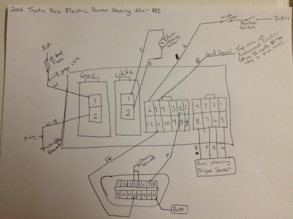
I have been in email contact with the original poster (his name is Jared) of that thread. Here is a more complete pin-out for the Yaris steering ECU:
This is a wiring diagram that Jared put together.
Jared solved the CAN signal issue by using and custom programming the CANdo Auto Module:
http://www.cananalyser.co.uk/candoauto.html
Here is an excerpt from his post on the Toyota forum:
"I going to jump into technical which will make much more sense once you research the CAN system. I was able to find the hex decimal code for engine RPM is 2C4 wheel speed is either 0B0 or 0B2. Since my setup has a non ABS eps ecu has an analog wheel speed signal (input). I only needed the engine RPM on the CAN network so i will only go over how I programed the Cando for this. The Cando has 2 analog inputs that can be programed to then transmit programable CAN data. It also can have ten static data points programed and continually repeated. When you get the software open there are four tabs. "Input view", "Input setup", "CAN transmit" and "CAN setup" first off we need to go to "CAN setup" and change the setting to 500kps to match the network speed of the CAN system. Then back to the tab "CAN transmit". Now as I said earlier the hex for RPM is 2C4. The data length is 11 bit. The dlc is 8. The information I used was ramdomly picked after much trial and error. Almost 3 pages of codes I tried. I could set the RPM in connect my scan tool and see the RPM but still no assist. After much frustration I finally realised that it was a setting I had wrong. It was how often I had it repetting the message. The end result looked something like this 2C4 8 06 8A 00 19 00 00 92 09 Repeat rate 20 ms(milliseconds). All this done and turned the car on and immediate assist. I still have not been able to drive the car and see if it feels bettter. Still working on some idle issues with the engine. I could however tell the assist was greater. Last thing to work on is connecting the CAN wiring to the DLC so i can see about changing the setting for the assist level at idle."
What makes this more frustrating for me is that the Holley Dominator does use CAN communication. This is used for communication with Racepak and the Holley digital displays. The frustrating part is that the Holley CAN protocol is proprietary, so the odds of the Yaris steering computer "understanding" the Holley data packets are nil.
Before I go down the same path as Jared, I need to have a conversation with DCE. Their Microsteer ECU is speed sensitive. The only question remains is if the Microsteer ECU is compatible with the Toyota motor. If it is compatible, then I am inclined to ditch the Toyota ECU and simplify this ordeal by spending money on the Microsteer ECU instead of buying the CANdo box. I also need to find out how DCE handles the torque sensor center point calibration, as this seems rather important for obtaining satisfactory on-center feel and return.
I am open to thoughts and suggestions!!!
|
|
By kevink1955 - 8 Years Ago
|
Andrew
I have not found any other pin that will wake the unit up, Only way I have found is to pulse the VSS pin
What you found about needing the canbus RPM signal would need to be proven before I would believe it. I have proven there are 3 levels of assist and do not think it does any more.
On the wheel return issue, I do not have any issue with that, my wheel returns almost to center on it's own but it always did as I have more + caster then the spec calls for. If you unplug the motor from the ECU does the wheel return any better? You have to remember for the wheel to return the steering gear has to drive the worm gear on the motor I always thought you could not drive a worm backwards, thats why they use them in winches. Their is no way that the ECU can assist in wheel return as there is no way for it to know the steering gear is trying to return, the torque sensor is on the wrong side of the unit for that. The only way that the return can be hindered is if the ECU shorted the motor leads loading down the motors ability to generate reverse voltage, unplug the motor for a test.
There was something else but I do not remember what it was, I will in my sleep tonight and will reply LOL
Till Later Kevin
|
|
By andrewb70 - 8 Years Ago
|
Kevin,
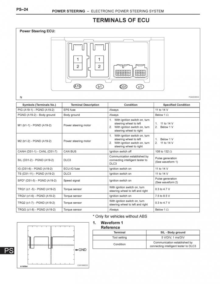
I firmly believe in your bench testing and it has been invaluable!!! What concerns me is the failsafe chart from the Toyota FSM. See below:

See code U0105. What is not clear is if this code is set for a non-ABS steering ECU. This is another reason why I can to be able to establish communication with the steering ECU through a OBDII connector. With that connection established, I should be able to read code, clear codes, and do the torque sensor zero point calibration. This seems valuable for many reasons.
Andrew
|
|
By kevink1955 - 8 Years Ago
|
Andrew
The next code down U0121 ABS communications error leads me to believe that that chart is for a Yarus or Prius with ABS. We are working with a NON ABS Yarus steering ECU
We have already proven there are 3 levels of assist where the chart state both codes will result in a fixed 43 mph assist level
Kevin
|
|
By andrewb70 - 8 Years Ago
|
That picture is right out of the FSM for a 2007 Yaris. At various points in the manual it references both steering with the ABS and the non-ABS steering computers.
I might be over thinking this, but I going to get all of the connections made between the steering ECU and the DLC3 connector. I am have also talked to a car buddy/computer geek, and he is going to make a Arduino powered CAN simulator. He has done this before and feels it is totally doable. The CAN simulator will act as the other terminator for the CAN network (in the Yaris FSM it is very clear that the engine ECM is one end of the CAN bus and the SP ECU is the other end). The CAN simulator will be programmed to send a constant RPM signal so that the steering ECU thinks the engine is running.
Today I also happened to be walking out of the store when a Yaris pulls into the parking lot. I approached the driver and asked if he had power steering with the key ON and engine OFF. He wasn't sure, but we tested it, and sure enough, no power steering until the engine starts.
The reason that I am going through all of this trouble is to make the steering ECU happy and not set codes. The reason we can't have codes is because if there are any codes, the ECU is not going to perform the torque sensor zero point calibration. I really want to perform this and see if the return to center improves. Also, as noted in the codes chart, if the steering ECU is throwing those codes, I do not believe that speed sensitive steering is active.
Andrew
|
|
By kevink1955 - 8 Years Ago
|
Andrew
I would not expect a Yarus to have power steering with just the key on. If it's Non ABS we know for sure that it needs VSS pulses and you are working on proving the CanBus RPM signal is needed.
Have you tried unplugging the motor from the ECU to test the return to center, If return to center is still slow unplugged I do not think anything you do will improve that. Remember, you are driving a worm gear with the steering shaft and while the out of the car tests indicate the EPAS shafts turn with very little resistance is this what is slowing the return ??
Kevin
|
|
By andrewb70 - 8 Years Ago
|
I asked the kid that was driving the Yaris today and his does have ABS.
I have unplugged the motor before and taken a spin around the block. It was the worst possible scenario. Super high steering effort and a very...very poor return to center. Way worse than with the motor plugged in.
I will think about all of this some more as I travel tomorrow and enjoy some turkey on Thursday. I hope everyone has a great Thanksgiving holiday!!!
Andrew
|
|
By kevink1955 - 8 Years Ago
|
Andrew
Ok,so the Yarus has ABS so the only way it could turn on is VIA CanBus and we assume it gets an RPM and when moving VSS so I guess it is expected that it would not turn on with just ignition.
The motor unplugged is kind of unexpected, I was not aware that the ECU provided any power to the motor on return. I will try to play with that a little over the holiday but it will be with a Prius ECU. Just to confirm, you had the motor unplugged from the ECU, not the power to the ECU? Please confirm this for me
Enjoy your Thanksgiving, we will be at home so if I need an escape I may find time to play a little.
Kevin
|
|
By kevink1955 - 8 Years Ago
|
Andrew
I did find the Yarus ECU and found the following
For these tests a Prius steering motor and gear box were strapped down to the workbench with 8" Vicegrips on the input and output shafts.
With the ECU enabled via VSS pulses turning the output shaft (as it would be on wheel return) is met with very slight resistance, slightly restraining the input shaft (like a tight upper column bearing would do) greatly increases the resistance as the torque sensor is trying to counter the the input.
On powering down the ECU, the same very slight resistance is still felt. If you unplug the motor from the ECU most of the resistance goes away, only the rotating resistance of the gears and motor remains.
Putting an ammeter in series with the motor and the ECU shows about 500MA of current when the output shaft is rotated and the motor becomes a generator
Putting a dead short on the motor leads makes it very hard to rotate the output shaft.
My conclusion is that the ECU presents a slight electrical load to the motor when it is is being driven by the output shaft and is generating reverse current but I do not feel this very slight restance inhibts steering return very much if at all.
What I to find will inhibit return is a tight upper column bearing as the torque sensor picks this up as steering wheel input counter to the direction of shaft rotation bringing on assist to counter it.
If you has the entire original column to work with remember the top bearing, it was a very good quality shielded ball bearing, I wonder if that's why. Thinking further, the Mustang has 2 horn brushes where the Yarus has a clock spring , I Assume the Cougar is the same as the mustang. Could the brushes plus a slightly binding upper bearing cause this??
You still have to tell me what happens when you unplug the motor leads from the ECU, does the wheel return get better??
Let me know your thoughts Kevin
|
|
By andrewb70 - 8 Years Ago
|
kevink1955 (11/23/2018)
Andrew I did find the Yarus ECU and found the following For these tests a Prius steering motor and gear box were strapped down to the workbench with 8" Vicegrips on the input and output shafts. With the ECU enabled via VSS pulses turning the output shaft (as it would be on wheel return) is met with very slight resistance, slightly restraining the input shaft (like a tight upper column bearing would do) greatly increases the resistance as the torque sensor is trying to counter the the input. On powering down the ECU, the same very slight resistance is still felt. If you unplug the motor from the ECU most of the resistance goes away, only the rotating resistance of the gears and motor remains. Putting an ammeter in series with the motor and the ECU shows about 500MA of current when the output shaft is rotated and the motor becomes a generator Putting a dead short on the motor leads makes it very hard to rotate the output shaft. My conclusion is that the ECU presents a slight electrical load to the motor when it is is being driven by the output shaft and is generating reverse current but I do not feel this very slight restance inhibts steering return very much if at all. What I to find will inhibit return is a tight upper column bearing as the torque sensor picks this up as steering wheel input counter to the direction of shaft rotation bringing on assist to counter it. If you has the entire original column to work with remember the top bearing, it was a very good quality shielded ball bearing, I wonder if that's why. Thinking further, the Mustang has 2 horn brushes where the Yarus has a clock spring , I Assume the Cougar is the same as the mustang. Could the brushes plus a slightly binding upper bearing cause this?? You still have to tell me what happens when you unplug the motor leads from the ECU, does the wheel return get better?? Let me know your thoughts Kevin
Kevin,
I did drive without power to the motor and the return to center is even worse than with power applied.
The Cougar turn signal switch is exactly the same as the Mustang, so there are two horn contact brushes. I just installed a new turn signal switch and I can't imagine that the horn contact brushes are the cause.
What might be happening is that the way I have the upper column tube being attached to the Toyota motor is causing some bind in the upper shaft. I am going to revisit this further in the future. The collar that I welded to the upper tube only has one set screw, so when that set screw is tightened, I think this puts some bind on the upper shaft. I think a way to solve this is to install two more set screws (so 3 set screws are 120 degrees apart) and tighten them evenly to keep the upper tube square and concentric with the Toyota motor.
Andrew
|
|
By kevink1955 - 8 Years Ago
|
I see on the other site that you have some projects going with CanBus, let us know if and how it works out
I am still puzzled by the poor return with the motor unplugged as it is opposite what I find on the bench.
Just to be sure You have the motor unplugged from the ECU and not the ECU unplugged from the power connector, correct
Hope to hear of some progress Kevin
|
|
By andrewb70 - 8 Years Ago
|
kevink1955 (11/30/2018)
I see on the other site that you have some projects going with CanBus, let us know if and how it works out I am still puzzled by the poor return with the motor unplugged as it is opposite what I find on the bench. Just to be sure You have the motor unplugged from the ECU and not the ECU unplugged from the power connector, correct Hope to hear of some progress Kevin
Kevin,
Now that you mention it, I actually do not recall if I unplugged the motor from the ECU, or if I unplugged the power going to the ECU. I will try this again, making sure to unplug the motor from the ECU as you have suggested.
Yesterday I received the CAN simulator from Blake and last Friday I got the necessary connectors to build the harness.

I got the two Molex connectors for the box itself along with an OBDII connector.
Blake also emailed the pin-out diagram.
I am still sorting out exactly how I am going to do the wiring, but I am hoping to wire things up temporarily tomorrow and see what sort of trouble I get myself into.
If the power steering comes on when the CAN simulator is turned on, then I know it is working.
The other part of this will involve hooking up an OBDII scanner and seeing what codes are being sent by the steering ECU. I am hoping that I can do that with my BlueDriver Bluetooth dongle and my cell phone. Hopefully it will also let me reset the codes.
Wish me luck!
Andrew
|
|
By kevink1955 - 8 Years Ago
|
Andrew
Sounds good, let us know if the wake up on canbus works, you already have the most high tech 67 Cougar on the planet. This will just be the next step.
And yes there is considerable difference steering motor unplugged from ECU VS removing power from ECU and leaving motor connected. If you want to see some really high effort steering short the unplugged motor leads and try turning the wheel. The motor becomes a generator when driven and the short loads it down real bad.
Kevin
|
|
By andrewb70 - 8 Years Ago
|
Today I was able to do some testing. I didn't want to wire everything up permanently only to have to chase things down later. So today I simply wanted to see if Blake's box works. The definition of "works" is, will the steering ECU turn on when it sees an RPM signal over CAN. I wanted to do more, but I didn't have enough terminals for the little connector that plugs into the steering ECU. There is a Prius at a junk yard not to far from me. I plan to take a trip and see what I can rob off it.
I connected the CANHi and CANLo at the steering ECU (on the D31 connector) to the CANHi and CANLo on Blake's box, making sure to twist the wires. I installed the wires into the Molex connectors for power and ground, ran the ground under the dash and had the power wire ready to connect to a temporary power source.
I turned the ignition ON, and as expected, there was no power assist. As soon as I applied power to Blake's box, almost instant assist. Blake said that his box should come online in less than a second, and that's about right.
I then went for a drive, not really expecting any difference, but to my surprise, there was a difference. At low speed there is considerably more assist and as speed increases there is a noticeable drop in assist. So contrary to my previous proclamations, and counter to the results that some people have done with bench testing, I don't believe that the speed sensitive steering is active if there is no CAN signal. This makes sense, because in the Yaris FSM it clearly states that if there is a CAN communication error with the engine ECM, it defaults into "failsafe" mode (fixed assist at the middle level). The RTC was about the same, but I expect this to improve once I get the OBDII connector wired up, scan and clear any codes, and perform the torque sensor zero point calibration.
Progress is being made.
|
|
By kevink1955 - 8 Years Ago
|
Andrew, sounds good. A assume you are still applying VSS from the Holly and that is what is changing the assist level. I still contend that with VSS only I have felt 3 levels of assist on the test bench. Waiting to see how the Diagnostic connector works out. You have a better test bed in the Cougar than I have on the bench.
Keep us posted Kevin
|
|
By andrewb70 - 8 Years Ago
|
Kevin,
Yes, the speed signal is still coming from the Holley Dominator ECU. I believe what you tell me, but at the same time I can't deny what happened today. Clearly more testing is required, and I plan to do that once everything is installed for good. I am really eager to get the OBDII port wired up and get it functioning and check for codes.
I actually managed to find the tiny little terminals that go into the D31 connector. They are made by Tyco and I ordered some from DigiKey. No sense in going through all this and not doing the wiring the best that I can. I also tracked down the D31 connector body in the Yaris FSM and it is available from the local Toyota dealer for $7.
The plan is to use a spare hot lead that I already wired from the engine bay to under the dash. That wire will power (through a relay) the steering ECU turn on circuit on pin 6 (2.5 amp fuse), Blake's box (5 amp fuse), and the OBD2 connector (7.5 amp fuse). I will trigger that relay through the Holley Dominator, so as soon as the ECU powers, Blake's box goes live, and so does the steering ECU.
For New Years I am visiting a friend in Orlando. He is a sharp guy and has a well equipped shop. One of the things that we will try to do on the trip is check both the upper and lower shafts and make sure they are laser straight. I know my top shaft is not perfect and the bottom one might need a tweak as well. Not having those shafts perfectly straight is definitely hurting RTC. The other thing that we are going to see about doing is making a beefy bracket to support the column at the motor. He is an excellent fabricator and I am sure we can come up with something that can be welded to the pedal support bracket and anchors the motor assembly. I think having the column be as rigid as possible will also improve the installation and overall driving experience.
Andrew
|
|
By andrewb70 - 8 Years Ago
|
Just a tiny little update. The weather has been cold and rainy, so no work is being done, but I did receive some parts. I like doing a proper wiring job and that means not doing any butt connections with the wires if it can possibly be avoided. This means spending some time looking at catalogs and data sheets for the right terminals.
With the Yaris (and Prius) steering ECUs the wiring that needs to happen is on the D31 connector. This is where the +12v power pin is located, along with the speed signal, CANHi and CANLo, etc....I have a D31 connector that I clipped from the donor car so what I needed were the actual terminals to avoid butt splicing wires and to add pins as needed. I was also looking to find the connector itself, but had no luck, but the Toyota dealership has them for $6. However, the dealership does not have and can't even look up the terminals. As far as I could tell the connector is made by TE Connectivity and the stock terminals had Tyco stamped on it. A little time spent in the TE Connectivity catalog resulted in a reward.
I know this may seem like overkill for most people, but if I am going to all this trouble, I might as well take it 100% of the way.


Once I get a dry sunny day, I can wire up the rest of the wires for the OBD2 connector and see if I can read fault code using the Blue Driver OBD2 dongle and android app.
|
|
By kevink1955 - 8 Years Ago
|
Andrew
It's not over kill, it's doing it right and in a way that will last. Nothing worse than spending a few hours under the dash troubleshooting a problem caused by a splice that should not have been there in the first place
As always, please keep us updated Kevin
|
|
By dominic-ch - 7 Years Ago
|
We have put this same EPS into a couple of MGAs and I would be REALLY happy to get the part numbers for the Toyota plug and the TE Connectivity terminals so we can order them as well - have sent Andrew a private message as well
Thanks
Dominic
|
|
By dominic-ch - 7 Years Ago
|
BTW, now having read all this thread I can provide some feedback on the issue of re-centering the steering. In the experience we have, this is not necessary if the ECU and column are a pair from the donor car. If you get a mismatched set, then the re-centering will be needed, otherwise the steering centering works as if it was still in the donor car. So make sure to get a paired set from your donor / breaker
|
|
By andrewb70 - 7 Years Ago
|
I am sorry for not responding sooner. I am not a regular visitor to this forum and it does not send out emails when there is a post or PM.
The D31 connector PN is 90980–12290 and can be ordered at the Toyota dealer for about 7 bucks. The terminals are TE Connectivity PN 1674311-1 and can be sourced from DigiKey.
The information below is not confirmed first hand, so proceed accordingly. I might as well add the information for the A19 (power connector). The connector body can be bought from Toyota under PN 90980-12300. This is a connector made by Yazaki and I have not found a company in the US that sells the terminals individually. However, I believe these are the terminals and can be ordered from Japan:
***EDIT*** THIS TERMINAL IS NOT CORRECT*** 2/10/19
https://global.rakuten.com/en/store/auc-hi-1000/item/f312-yz-5080/
***EDIT*** THIS CONNECTOR IS CORRECT*** 2/10/19 ***The same vendor has the connector bodies:
https://global.rakuten.com/en/store/auc-hi-1000/item/2p375-a-yz-f-tr/?l-id=rgm_item_en_rvp_widget
Andrew
|
|
By andrewb70 - 7 Years Ago
|
The links I posted in my last post seem to have the right parts. I found these pictures that I took:


|
|
By dominic-ch - 7 Years Ago
|
|
Have bought the connectors and body from Japan, and will post here when they arrive to confirm if they fit....
|
|
By dominic-ch - 7 Years Ago
|
Pin for the D31 connector is Toyota 82998-12750 or -12760
The power plug housing is 90980-12300 - still looking to find a Toyota part number for the 9.5mm 312 connector it holds
|
|
By andrewb70 - 7 Years Ago
|
I ordered parts from Japan as well and will post results when I receive them. However, the vendor sent me pictures and I am fairly confident that the parts are correct.
Andrew
|
|
By andrewb70 - 7 Years Ago
|
Quick post. The connector body from Japan was correct, but the terminals were not.
Andrew
|
|
By dominic-ch - 7 Years Ago
|
With some Japanese language help, this seems to be the correct female terminal for the A19 connector housing that Andrew confirms is correct
From the same supplier as the housing to save by combining shipping costs
the correct terminal number from Rakuten f375-yz-s direct link is item.rakuten.co.jp/auc-hi-1000/f375-yz-s/ As this is linked directly from the connector housing page we are 100% confident it's correct
For those outside the USA, the Toyota part numbers are not available in the European parts system, so I had to find a US supplier that would deliver to me in Switzerland. I found megazip.net. This also has all the parts diagrams for all models online - they do seem to be very slow to process orders however.... 6 days since ordering and still not shipped.....
|
|
By andrewb70 - 7 Years Ago
|
This terminal:
item.rakuten.co.jp/auc-hi-1000/f375-yz-s/
is correct in that it fits the connector, however it is designed only for 12 gauge (3mm) wire. The correct terminal must be designed for 5-8mm wire. Thus far, that particular variant has been elusive.
Andrew
|
|
By andrewb70 - 7 Years Ago
|
Not much to report in terms of progress or any other updates, however, I finally managed to track down the Yazaki part numbers for the big power connector for the steering ECU. The same connector is used on both the Prius and the Yaris steering ECUs (and probably others of the same vintage).
The connector housing body is 7283-3521-40

The terminals are either 7116-3097-02 or 7116-3098-02 (either will probably work).

The big challenge is sourcing the terminals in the US. The connector body can be purchased from Toyota under PN 90980-12653, however, Toyota does not sell the terminals.
I was actually able to source the connector housing bodies from Japan, but what I originally thought were the correct terminals, ended up being the wrong ones.
If anyone knows a source for Yazaki parts in the US, please let me know.
Andrew
|
|
By Lord Gaga - 7 Years Ago
|
"If anyone knows a source for Yazaki parts in the US, please let me know."
Just twist the wires together and wrap with masking tape! lol
|
|
By andrewb70 - 7 Years Ago
|
I recently completed a 1000 mile road trip in the Cougar and I noticed that the steering was particularly numb on center. While driving down the highway I found myself having to constantly steer it in order to keep it going straight. I attributed this mostly to the windy conditions that I encountered at various points on the trip, but I didn't give it much more thought.
After getting home, I noticed that there was a little squeaking noise from the front end when I made slow right hand turns. I suspected that maybe the preload on the front bearings has loosened up, so I jacked it up to investigate. Rocking the wheel at the 12 and 6 o'clock position really didn't show any unusual looseness in the bearings, however, I did find significant slop when I rocked the wheel at the 3 and 9 o'clock positions:
https://www.youtube.com/watch?v=PcJwicXdsmc
Although all of my front end components are "new" they do have about 15K miles on them since installation. After seeing the slop in the rack, I called TCP and was surprised and pleased to get a live tech guy on the line. His name was Mike and he was very helpful. He told me that due to the straight cut gears of the rack and pinion gears, periodic inspection and adjustment is necessary to minimize the backlash. He outlined the procedure and I went outside and did it. I also noticed that the passenger side inner tie rod was a little loose where it was bolted to the rack, and I was able to address that.
Needles to say, the steering feels much better. The return to center is much improved and the on center feel is also much better (no duh...considering how much slop was there)! I plan to have the car up on a rack in the near future to inspect all of the steering and the suspension components and fix anything I find.
Take away: don't assume everything is tight and working properly just because all of the components are "new."
|