On with the Ford Follies!

Last night it was time to get the wiring harness going. If the weather is nice I try to get body work and paint completed. If it's raining then on with the things we can get done in the garage.
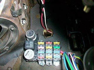
What we have here is a RebelWire brand aftermarket harness.
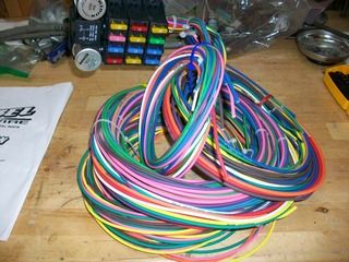
I chose RebelWire after looking at reviews, reading other forums, and checking out what they had available. I did not want to go with an original harness - too expensive and there would not be fuse panel, not enough circuits for what we are adding here, etc. RebelWire is made in the USA from what I am told, and from what I have read the customers who write on forums like this one appreciate the customer service with RebelWire in case there are any problems. Each wire is laid out with its intended use/circuit labeled every 6" along the insulation. The kit comes with the main loom and panel, is zip tied (color coordinated in that regard) per bundled use, a separate bag for the alternator and other accessories, and of course instructions. There are no terminals with the kit.
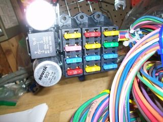
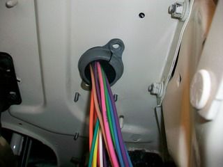
Ok so first up was to choose a location for that fuse panel. You can see in the photo below where I chose to place the panel. It seemed reasonable enough and will not be too hard to read/replace fuses when needed. The only hitch was that ALL wires exited to the right of the loom - headed straight for the main pedal bracket! (more on that later).
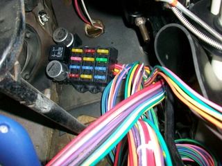
What a mess of wires coming out of that small panel!
Time to take a break and get a Ford Follies story. Take a look at this photo and guess what happened...
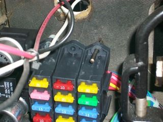
Yep, dufus me - while drilling the third hole to mount the panel to the firewall my drill bit came loose from the keyless chuck in my cordless drill! :mad: Nice. I will have to say that while I like the location of the fuse panel it was a joke with all of the contortions and octopus-like positions I had to be in to secure everything under there. A real show. Me and the 55 playing a round of "Twister" :eek: Thankfully this is not a reality TV show but I would bet people would pay money to see the unplanned goofs and what have you!
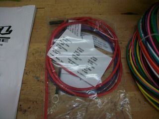
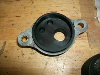
Take a look at the following photo to see how I solved the issue of the wires exiting to the right...
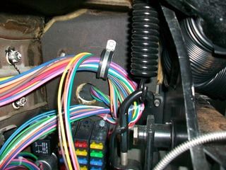
With that small piece of hardware, the wires were brought up and back to the left - especially those wires going to the ignition and headlight switches. Trust me, there was plenty of wire in there to reach to the steering wheel if needed, and the loom that ran to the steering wheel could reach the front seat easily.
So what was it like at the firewall in the engine bay? Could we use the original rubber grommet and keep things pretty clean looking?
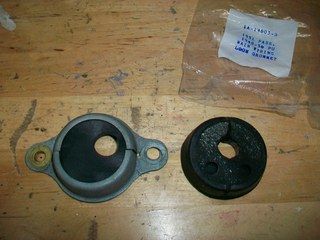
I had my doubts - there were a lot of wires coming out of there!
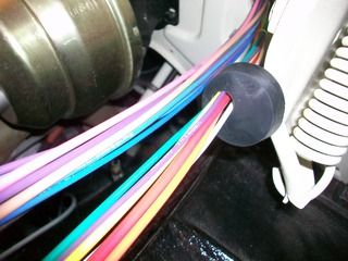
So, I started with one run of the loom and that fit pretty well. I looked at the other and noticed that there were splices to run through where the end of the run had two wires but that same line had one wire at the firewall. This.just.might.work.
And so it did! Nice and tight too so that it held pretty easily at the firewall.
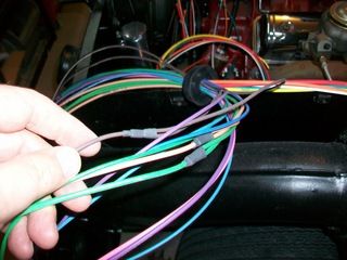
But now look at this mess!
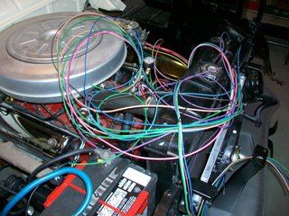
Although it looks bad I really don't think there is going to be too much problem here. The instructions read pretty well and the lines are all marked every 6".
This afternoon was very nice outside so I finished removing all of the paint (and a little rust) from the hood outside, and I cleaned up the shop for some friends coming over later on this week. (Needed to put new gloves in the blast cabinet and a new lens as well)
More Ford Follies coming soon...
Daniel JessupLancaster, California
aka "The Hot Rod Reverend" 
check out the 1955 Ford Fairlane build at www.hotrodreverend.com