Here it is May 7th and I feel like I've got nothing done! My air compressor (the heart beat of the shop) went down and I chase the problem for a week or so. It ended up being the start capacitor. No biggie, get it ordered, be here in 4 days, etc. Capacitor shows up - wrong one. Right box, right label, wrong capacitor in the box! Aaarrrrrggghhhh, another 4 days and we have what we need.
Pressure washer went crazy blowing water everywhere. Seems Karcher uses a lot of molded, high density pvc in their units - this one had a cracked elbow. 5 days and replaced that.
My wife drove through some truckers' explosion and she says the smoke and debris made it where she could not see a thing, van covered in all kinds of good, plastic?, black dots, and I don't know what all. 10 hours of a buff job and we are all shiny again - just in time for Mother's Day.

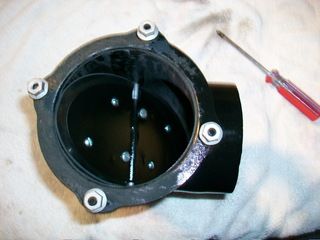
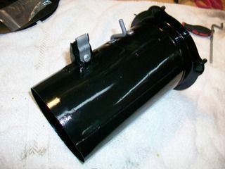
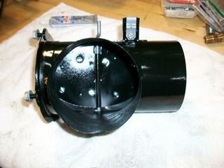
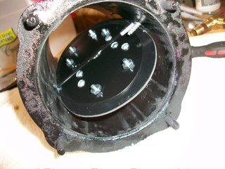
I did get those vents squared away. They look good. The seals went into the units without much fanfare, and I put a tick of white lithium grease on the pivots.
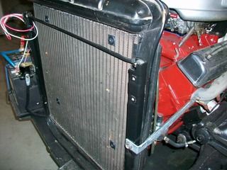
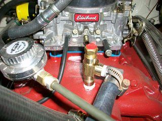
I also got a chance to mount an electric fan and plumbed a thermostatic switch after a visit to Lowe's and the plumbing section. You can see the tee I put in right there behind the thermostat housing on the intake. I could not figure a way to get a good tee and still have good access if I used the original sending unit location on the head at the rear (there is already a sending unit there for the mechanical gauge.)
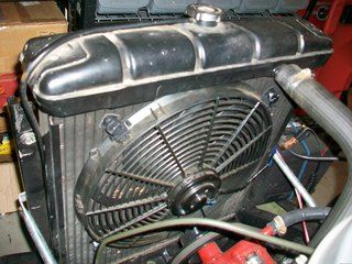
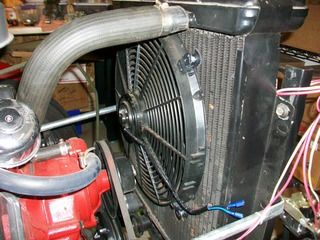
The electric fan went in without too much trouble as well. It is a pretty good unit that I had been using on my portable engine run stand. Would you believe you can get a very good mounting kit on ebay shipped to you for $1? that's right, that's what it cost me - and it looked pretty healthy too and held up that fan nice and tight.
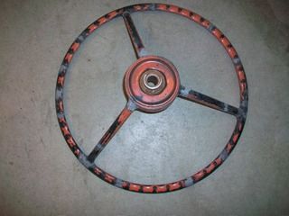
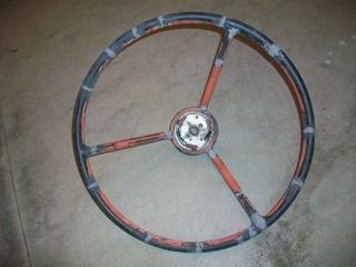
And then we have everyone's favorite job - the dreaded steering wheel! :o
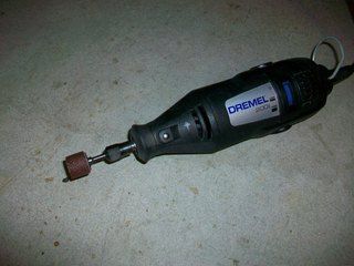
I used PC7 epoxy to fill in those cracks and crevices after opening them up and then took a dremel tool to the thing to sand it as level as I dared...ended up using a drum roll. (queue stupid joke :rolleyes

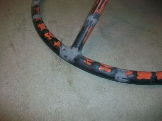
After I knocked down every bulge I took 120 grit sandpaper to it. Once I got down with the whole hour and a half job (man this is tedious work!) I was a dusty mess! Good thing I used a dual cartridge filter mask. I need to paint the wheel with some primer/surfacer after wiping it down with Acetone. After that I will probably have to fill in some low spots here or there with some glaze. I am not going to spend a whole lot of time on it - it is a driver after all not a show car.
Plan to see my father-in-law soon, but it looks like it will still be a little while before the 55 is back on the road...
Daniel JessupLancaster, California
aka "The Hot Rod Reverend" 
check out the 1955 Ford Fairlane build at www.hotrodreverend.com