|
Author
|
Message
|
|
charliemccraney
|
|
|
Group: Moderators
Last Active: Yesterday
Posts: 6.1K,
Visits: 442.8K
|
I'm about ready to start work on the windage tray and crankshaft scraper. What gauge steel should I use for them? I am getting a screen kit from canton racing products. I need to make a frame on which I can mount the screen? I found some ARP standoff studs for Chrysler that look like they will work.
Lawrenceville, GA
|
|
|
|
|
Glen Henderson
|
|
|
Group: Forum Members
Last Active: 9 Years Ago
Posts: 1.4K,
Visits: 7.5K
|
Charlie, I would juess that 18 gauge would work, 16 gauge would be better but harder to work if you are trying to form it. Please take some good pictures and a play by play as I want to try my hand at fab'ing one myself. Good luck!
Glen Henderson
Freedom is not Free
Letohatchee, AL
|
|
|
|
|
MoonShadow
|
|
|
Group: Forum Members
Last Active: Yesterday
Posts: 4.6K,
Visits: 38.4K
|
Talk to Ted. He made a few built to be trapped between the pan and block. Used longer pan bolts. Since the main caps are recessed this is a pretty simple way to mount it. It would certainly be handy to have a CAD drawing posted here someplace with details and pictures. Then we could decide whether to build one too. Thanks, Chuck
Y's guys rule!
Looking for McCullouch VS57 brackets and parts. Also looking for 28 Chrysler series 72 parts. And early Hemi parts.
MoonShadow, 292 w/McCulloch, 28 Chrysler Roadster, 354 Hemi)
Manchester, New Hampshire
|
|
|
|
|
charliemccraney
|
|
|
Group: Moderators
Last Active: Yesterday
Posts: 6.1K,
Visits: 442.8K
|
Where is Ted? He hasn't been on since the 25th.
Lawrenceville, GA
|
|
|
|
|
Ted
|
|
|
Group: Administrators
Last Active: Yesterday
Posts: 7.5K,
Visits: 205.8K
|
charliemccraney (4/24/2007)
I'm about ready to start work on the windage tray and crankshaft scraper. What gauge steel should I use for them? I am getting a screen kit from canton racing products. I need to make a frame on which I can mount the screen?
I found some ARP standoff studs for Chrysler that look like they will work.The one piece sandwich style windage tray used in the 428CJ engines is stamped out of 18 gage material. If making a frame to support the screen material, then 16 gage material would likely be more suitable. I've yet to make a simple windage tray in this design but the EMC engine project would need one that sandwiches between the pan and the block in which to fit the rules. Up to now, I've either installed the windage tray in the pan or incorporated it in the 'main support girdle'.
  Lorena, Texas (South of Waco) Lorena, Texas (South of Waco)
|
|
|
|
|
charliemccraney
|
|
|
Group: Moderators
Last Active: Yesterday
Posts: 6.1K,
Visits: 442.8K
|
Thanks Ted. I have a few more questions. I sent them to you in a pm but I'm not sure if you got it. I notice that most trays are curved and some are not. Is there any benefit of one design over another? Because of the deep skirted design, I am thinking that a curved tray is not necessary - or at least not much of a curve will be required. The old airhead BMW motorcycles use flat windage trays. Does the distance between the tray and rotating assembly affect how well the tray functions? How much clearance is required between a crank scraper and the rotating parts? Does a scraper function better on one side of the block than the other.
Lawrenceville, GA
|
|
|
|
|
Hoosier Hurricane
|
|
|
Group: Moderators
Last Active: 4 hours ago
Posts: 3.7K,
Visits: 323.0K
|
Charlie and Ted: The scraper I use in the Hurricane sandwiches between the block and pan. I took a piece of thin cardboard the length of the block (not including the timing cover) and about 3 inches wide, and put holes in it so that pan bolts and flat washers would hold it in place. It is on the passenger side of the block. I rotated the engine backwards and trimmed the cardboard as needed to clear the rotating parts. I kept the clearance at about 1/8". I transferred the pattern to some 18 gauge and cut it out. Put it back on the engine and double checked clearances. I left tabs on the scraper that align with the main caps and they rest on the bolt heads. Then I took another piece of 18 gauge the length of the scraper and rolled a radius of about 2" on it lengthwise. I trimmed the rear corner so it would fit into the pan, and fastened it to the bottom side of the scraper. I did this to keep the scraped oil from slamming against the pan gasket, and to direct the oil downward to the pan. I have screen in the pan made from 1/8" hardware cloth. I don't know how much horsepower I gained, but when I installed it my car picked up 1/10th sec. in the quarter. Charlie, put the scraper on the passenger side. If it is on the other side, oil would pile up on top of it and have to keep circulating around and around. John
John - "The Hoosier Hurricane"

|
|
|
|
|
GREENBIRD56
|
|
|
Group: Forum Members
Last Active: Last Year
Posts: 1.7K,
Visits: 102.7K
|
If you guys can come up with a sketch, set of dimensions, tin thickness etc. - I'll try to get a good CAD drawing made so that it can be put out in the available Y tech information. We'll just put note on it that it is copyrighted to the site or something. It may need to be handed back and forth a few times for checking to insure it is exactly what it needs to be. A 10th is worth working for if you are a racer - the big gains are probably at the upper end of the rpm band however - not especially street horsepower. Dyno guys would know best. On the other hand - the crank scrapers are a pretty simple part and who knows - maybe it'll be just enough to dust a contender. Here in Tucson, I get sheetmetal shims and plates (often up to .250 thickness) cut by a guy with a Laser - and there are several other businesses around elsewhere that can do the same thing. Lately we have had some heavier harder stuff cut with a 50,000 psi waterjet. They just need a decent drawing to get it set up on XY coordinates. As a lifetime garage dweller - I'd probably try to make my own first....................

Steve Metzger Tucson, Arizona
|
|
|
|
|
Hoosier Hurricane
|
|
|
Group: Moderators
Last Active: 4 hours ago
Posts: 3.7K,
Visits: 323.0K
|
Steve: Cad drawings sound good, however every stroke, and every rod configuration would require different depths of scallops on the leading edge, so development time would be considerable, and several folks would have to make patterns of the different bottom ends and make them available. Mine is for a 3.44 stroke and C2AE rods with palnuts. I loaned mine to Rick Coder to copy, but I'm not sure he did, he probably just looked at how it was made. As an aircraft mechanic, he has access to sheet metal and the machines to form it. I'll bet his looks a lot more professional than mine. I think you're right, the biggest help is in the upper RPM range, both in cutting windage and getting oil back to the pan quicker. Street gains would be small. Peace of mind would be present, though. John
John - "The Hoosier Hurricane"
|
|
|
|
|
charliemccraney
|
|
|
Group: Moderators
Last Active: Yesterday
Posts: 6.1K,
Visits: 442.8K
|
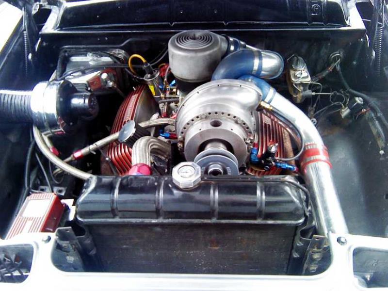
Thanks for the info, John. Steve, I plan to model it with CAD. I try to model all of the parts I make. As John says, it is not necessarily a universal thing. In my case it will be for a 3.47" stroke and aftermarket rods. I put one of the Chrysler studs in today. They are pretty long. I didn't have my oil pan with me to make sure that they don't interfere. Here's what it looks like. 
It's about 2 5/16" above the top of the main cap. That is with 14 threads in the block, which keeps the stud above the oil passage to the main. JM suggests that the threads go no farther than 1 1/8" in the assembly errors. 14 threads is about 1 1/16". I don't think the extra length will be a problem - so long as the oil pan fits. The only thing I can think of is how do I go about torquing the main nut? It looks like I'll need a real deep socket or a crows foot.
Lawrenceville, GA
|
|
|
|