|
By John Mummert - 13 Years Ago
|
One of the things we changed about the aluminum head was to move the rocker stand bolt closest to the intake manifold farther from the existing lower row.That left room to move the rocker shaft father from the valve making rocker ratios above 1.60:1 possible. This new rocker is longer from the roller to the shaft so it can't be used on factory heads.We just got our first set of samples of the new rockers
Modern 1.70:1 rocker ratio similar to all Ford V8 engines (except SBF) since 1958
With so many of the popular cam grinds being low lift designs this will put nearly all of them in the .450-.500" lift range.
Price has still to be determined.
|
|
By MoonShadow - 13 Years Ago
|
Darn John are you following in the steps of Edelbrock? Of course I mean Vic not the new kid. How many other secret developments do you have going? Should I wait a couple of years and save up for the all new aluminum 1000hp street gas Y-Block? Then I could just buy a Mummert crate enging and be done.  Chuck Chuck
|
|
By John Mummert - 13 Years Ago
|
|
Chuck, yeah I still have a few ideas in the works. Finding a good foundry that can do old school patterns has been a challenge. Will post them here as they get done to keep you guys on the cutting edge of vintage tech
|
|
By pegleg - 13 Years Ago
|
John Mummert (4/5/2013)
Finding a good foundry that can do old school patterns has been a challenge.
Think I heard that somewhere else.
|
|
By John Mummert - 13 Years Ago
|
|
Frank, is there some "I told you so" in that comment?
|
|
By pegleg - 13 Years Ago
|
|
Naw! I'm sure you told me that! I'm really glad you found a reliable source though, wish i coulda!
|
|
By John Mummert - 13 Years Ago
|
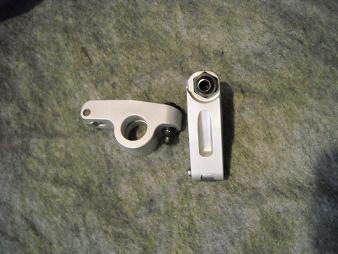
Put our new rockers to the test this weekend and was really happy with them.
The basic layout was to accomplish a few things.
1. Get more pushrod clearance
2. Add lift to many of the cam profiles we currently sell.
3. Keep base circle size up. Nose radius also improves
(Simply put being able to run smoother profiles. )
They assembled quickly using springs and shims. Of course they have their own stands as the shaft center is moved toward the intake manifold. We'll be running them through the next few races and inspecting them.
For now they are doing just what they should and I'm good with that.
|
|
By pegleg - 13 Years Ago
|
|
Investment casting ?
|
|
By John Mummert - 13 Years Ago
|
|
Frank, the rockers are 2024 billet aluminum, all CNC machined.The 1.7 ratio will take even a little E4 Iskenderian cam to .476 lift.
|
|
By pegleg - 13 Years Ago
|
|
Very pretty. Too bad i can't convince the tech inspectors at the Pure stock races that F codes came with aluminum heads and roller rockers. Probably be a tough sell!
|
|
By speedpro56 - 13 Years Ago
|
Paint the heads Frank, They'll never know the difference and I won't tell . .
|
|
By pegleg - 13 Years Ago
|
|
Gary, I expect those rocker arms would give the game away!
|
|
By charliemccraney - 13 Years Ago
|
|
What, do they make you remove your valve covers?
|
|
By marvh - 13 Years Ago
|
Speaking of rocker covers.
John;
Did you have to make any valve cover modifications to run those 1.7:1 rockers without hitting the valve covers.
I have 1.6:1 rockers and had to use the heavy rubber gaskets to clear the rockers adjusters with Edelbrock valve covers.
I guess with the 1.7:1 rockers the adjusters will be further inward so likely have more clearance.
marv
|
|
By speedpro56 - 13 Years Ago
|
Frank Frank!! you have to keep a straight face at all times. at all times.
|
|
By MoonShadow - 13 Years Ago
|
|
Considering that no respectable speed equipment house would EVER have made roller rockers for a lowly Y-Block they must be factory! Right? Sounds like a plan to me, what scrub or lopar fanatic would know any different? And if the inspector is a Y's guy he'll probably want to know where he can get a set. Chuck
|
|
By John Mummert - 13 Years Ago
|
Frank, these rockers are actually factory items. My uncle worked at factory and was in charge of destroying the experiments when they were through with them.They made 50 sets (so of course they are legal) of these but instead of destroying them he took them home. That's your story and I think you should stick to it.
|
|
By speedpro56 - 13 Years Ago
|
|
You see Frank, we're with you all the way in using these factory rockers.
|
|
By Hoosier Hurricane - 13 Years Ago
|
|
So if Frank buys a set of these rockers, and if I decide to again race my blown '57 Bird at the same race, then I'll have to have a set too. That way, when the inspector sees one set, he can check the other car to verify they are indeed two of the fifty sets that John's uncle "acquired". That inspector is a Pontiac guy, and the first time he teched my car he said, "I don't know what I'm looking at. I assume it's correct".
|
|
By MoonShadow - 13 Years Ago
|
|
And he has no idea how "correct" you car is John. Chuck
|
|
By pegleg - 13 Years Ago
|
|
John's right about Bobby-boo. He's definitely an Indian Freak. But, I'd have to have the heads too, and of course we all know the factory F codes ran ported (by Geoff Mummert) heads and roller rockers. What, you didn't know that? Well it's like all '57 Scrubs came with four speeds!
|
|
By PF Arcand - 13 Years Ago
|
|
Frank: Your remark about the 4 spd 57 Ch-v-s, reminds me that was one of the reasons that they got an undeserved big reputation in racing. As alluded to, "no" 57 Ch-v-s came factory acquipped with 4 spd transmissions! They were automatics or 3 spd close ratio transmissions. It didn't take long for some racers to aquire Corvette transmissions used or over the counter. At first they were illegal in stock classes.. then certain people who were close with G.M and in at least one case, a high ranking official in the NHRA, managed to weasel them in at some point as legal. Which was just dandy, cause neither Ford nor Chryler were supplying 4 speeds for their cars until later dates..
|
|
By pegleg - 13 Years Ago
|
You got it Paul. Don't forget the Sedan Deliveries with 4 speed Hydro's, not SlushGlides. After all the deliveries were trucks right? And the Trucks were built with Hydromatics! Besides, Ford had a three speed automatic so Chevy should have more than the PowerGlide for the automatic classes.
NHRA might have been a bit partial to the General! (Sarcasm)
|
|
By Y block Billy - 13 Years Ago
|
|
Back to the rockers, as you move the ratio higher the shaft gets closer to the pushrod end and further from the roller tip. The question is when doing this it multiplies the pressures on the lifters so when the ratio is increased do you use softer valve springs? If not I would think lifter and lobe wear would be drastically accelerated.
|
|
By Ted - 13 Years Ago
|
|
Y block Billy (5/13/2013)
Back to the rockers, as you move the ratio higher the shaft gets closer to the pushrod end and further from the roller tip. The question is when doing this it multiplies the pressures on the lifters so when the ratio is increased do you use softer valve springs? If not I would think lifter and lobe wear would be drastically accelerated.Pressure at the tappet increases in a linear fashion and is directly related to the increase in valve lift that’s accomplished by increasing the rocker ratio.
|
|
By NoShortcuts - 13 Years Ago
|
Hi Ted,
I'm sure that what you just said is correct, but I'm scratching my head. -No, I did not have a wild weekend! 
Is there any type of a numerical example that you might give to help me with my learning curve? I'm 'lost' on this one.
Thanks for your patience! 
Regards,
|
|
By pegleg - 13 Years Ago
|
|
If the spring is 200 lbs. at a given point, the pressure on the lifter is multiplied by the rocker ratio. So 200 X 1.54 = 308 #. If you'd run a 1.70 rocker then the pressure would be 340#s. Actually that's only part of the issue because the velocity of the valve, rocker , and pushrod AND the lifter all contribute to the forces the cam/ lifter interface sees.
|
|
By Ted - 13 Years Ago
|
|
NoShortcuts (5/13/2013)
Hi Ted, ... Is there any type of a numerical example that you might give to help me with my learning curve? I'm 'lost' on this one ....Frank has pretty much nailed how to calculate the actual load on the lifter based on the spring pressure. As a short cut and while not absolutely accurate, the valve spring over the nose pressures are typically used as a guide of what’s permissible for tappet loading. As a general rule, the valve spring pressure at 330-350 lbs is the limit for flat tappet camshafts. That would equate to 528-560 lbs actual pressure at the tappet using 1.6:1 rockers. But you’ll not hear the 560 lb value being used, only the 350 lb value. This is just a matter of semantics and the average person just needs to be aware of what the numbers actually represent so those numbers can be kept in their proper perspective.
Valve springs have a rate per inch value that can be used to calculate the amount of valve spring pressure at a given valve opening. It’s this value that can also be used to calculate ‘over the nose’ or lobe/tappet pressures. If the rate per inch isn’t known, it can be calculated from any two known compressed points on the spring. The linearity of the valve spring pressure rate makes this possible.
For a performance Y, the Isky p/n 165-A beehive valve springs are a popular choice so I’ll use it in this example. This spring is rated at 130lbs. @ 1.800” and 320 lbs. at 1.200. This is a 190 lb increase in pressure with a .600” lift. Doing the math for a 1.000” valve lift knowing these two values, the rate per inch would be 316.67 lbs. Going to the catalogue and looking up this spring shows its rate per inch listed at 310 lbs. While slightly different, it’s close enoughto be comfortable with using the catalogue value.
Knowing that particular rate per inch allows other valve spring compression values to be calculated. If the net valve lift is 0.531”, then the ‘over the nose’ pressure will be 130+ (.531 X 310) or 295 lbs. This is of course assuming the closed pressure is being set at the recommended 130 lb level. Likewise, if the net valve lift is 0.650”, then the ‘over the nose’ pressure will be 130+ (.650 X 310) or 332 lbs. If using my calculated value of 316.67, then the ‘over the nose’ pressure for the 0.650” lift cam will be 336 lbs. We’ll not quibble over 4 lbs. When in doubt, the valve spring pressures should always be checked with a valve spring tester at both the intended closed installed height and at the maximum valve opening.
|
|
By NoShortcuts - 13 Years Ago
|
Frank and Ted,
Thanks for the information. Truth be told I'm still absorbing what you've both shared.
GooD GrieF! The more I learn, the more I realize that I don't know! 
Regards,
|
|
By John Mummert - 13 Years Ago
|
One thing that should be added to the good info given is that the rocker arm is a tool. One might argue that the spring pressure would increase on a given lobe. But!! One must be looking at Pounds per square inch. A low ratio rocker forces you to go in all the wrong directions with the lobe. Because the bearing journals are a given dimension the lobe height cannot exceed this height. Resulting in reducing basecircle size for each thousandth of lift desired. Seeing that the lobe you are trying to grind on the core is a fixed shape every thousandth you reduce the basecircle the nose radius decreases right along with it. To understand how much stress is really on the nose of a lobe you calculate how much square area is contacting the lifter, figure out what percent of a square inch it is then divide your total spring pressure x rocker ratio by that. As an example 340 open lbs. x 1.54/ by .1" = 5236 lbs/in.. Now if you choose a lobe that has the same valve events with your new ratio the the lift can drop by 10% meaning the basecircle can increase by 20% 340 open lbs. x 1.7/ by .12"= 4816.66 lbs/in..
The other thing that should be looked at is where the load is applied to the lifter. Running more lift on a lobe of a given duration increases the lobes velocity there by placing the load farther out from the centerline of the lifter increasing the shear stresses on the stem and lifter bore. A higher ratio rocker increase valve lift without imposing this additional stress.
Please remember that these are for example figures. The simple point trying to be established is that fastest way to decrease lifter pressure is to increase the area of the wear face and keep it closer to the center of the lifter.
This new rocker arm set up is a tool. Allowing for greater selection of lobes to be used for street or racing use.. We believe this motor needs more options on the table.
Putting things into perspective Winston Cup or whatever its called today is still forced to run flat tappets and wear/ slash cam life is something they have been dealing with.. Bigger cam bearings allowing for bigger basecircles, high rocker ratios, high grade oils, etc. etc. are all part of their solutions.
As was mentioned before Ford Engineers shot up over 1.7 ratio by 1958 and rarely looked back..
FE, MEL, 385 Series(429-460), Cleveland, M Series, 3.8-4.2 V6, Boss 302 all used 1.7 or higher ratio from the factory.
|
|
By Ted - 13 Years Ago
|
|
John. Thanks for elaborating further on the additional forces that take place at the lobe/tappet. Good job on making that explanation as short as it was. Frank and I had pondered over whether it was a subject that should be touched upon but felt like it would be an overly complicated answer that would also be too lengthy to post. You managed to get the point across in a reasonably short explanation.
|
|
By charliemccraney - 13 Years Ago
|
No, it's no good because I now have more questions
Wouldn't the lifter be tangent (or whichever appropriate engineering term) to the lobe where they make contact, in which case the area cannot be calculated and the pressure should always be approximately the same? The only way the pressure could change with a larger base circle is if the cam or lifter surface deflect or perhaps the oil film transfers some of the load which can be represented as a surface area and that could conceivably increase with a larger base circle.
|
|
By pegleg - 13 Years Ago
|
|
Charlie, The larger base circle will allow a larger contact area with the lifter, and you can use less lobe lift resulting in a stronger camshaft.
|
|
By charliemccraney - 13 Years Ago
|
I understand how it is being represented.
By nature, I'm trying to understand the logic behind the math. If you take two curved surfaces and touch them together, the point of contact cannot have an area because it will be either a point or a line depending on the complexity of the curves. So where does the area come from?
|
|
By John Mummert - 13 Years Ago
|
|
Charlie a larger radius has more contact area than a smaller radius I can't think of a simpler way to put it. There is a difference between static or applied pressure and pressure in pounds per square inch. A sharp knife does more work than a dull knife with the same applied pressure. Simply because psi goes up on a sharp knife ,the cutting area is reduced and the static pressure the same.
|
|
By charliemccraney - 13 Years Ago
|
I guess I'll have to accept that "a larger radius has a larger contact area" is how this problem is modeled for engineering purposes, but in the simplest terms, any radius will contact only at a point or a line and those by definition have no area.
Take for instance a circle and a line that is tangent to that circle, where they make contact will be a single point, it doesn't matter how big the radius is, until it reaches infinity, it will always be a single point. Make that circle into a cylinder and the line into a plane. Now where they make contact can be represented by a line which has a length, but no width, and therefore, no area. The only way to have a contact area is if the edge of the circle or cylinder deflects to make more contact with the line or the plane. Do you see what I mean?
In terms of the cam and lifter, the larger radius will be flatter so perhaps the oil film is less inclined to disperse and effectively creates what can be considered a larger surface area. This also makes sense with the knife analogy, the cam will be less likely to cut through the film.
Since y'all didn't want to make it too complex, I'll just drop it from here.
|
|
By pegleg - 13 Years Ago
|
Charlie, you're right, but the flatter or larger radius does carry oil better. And the less severe angles deflect less and create lower forces at the intersection. Think about the clearance ramps on a flat tappet cam. Also, a lesson I still have trouble with, even metal deflects slightly under force. NOTHING is completely rigid. So in actuality there can be more area. Good luck trying to measure it though.
The reduction in friction must be large with rollers, many street Hydraulic cams have .600 or so lift and don't wear out quickly.
|
|
By John Mummert - 13 Years Ago
|
Charlie mechanical engineers use Hertzian Stress calculation for this type of useage everyday. This instance would use contact mechanics for an elastic sphere and an elastic cylinder. Where the lifter is the sphere and the cam lobe is the cylinder. Since all things made of metal have a density value this will be figured in along with the radius. The the 60" to 80" radius of the lifter will be figured along with a density value. The value of indent can be figured with weight of the lifter itself or under the load sping x rockers ratio thus an "area" can be determined for both weights as well as if the radius of the nose is changed. Metal parts do not have infinite hardness nor are we on the moon. I understand your theory of point or line contact but your theory says that there are no area differences in a cylindrical roller bearing or a ball bearing of the same diameter or ball bearing to ball bearing of any diameter. Yet all of these bearings have different load ratings and usages.
|
|
By charliemccraney - 13 Years Ago
|
|
Thank you, that is awesome. I realize what the simplicity of my example implies about the load rating of bearings and such but I also know that more area doesn't just come out of nowhere and something else has to be going on. That is really cool.
|
|
By Glen Henderson - 13 Years Ago
|
|
I always assumed that the reason lifters had a concave face, was to give more contact area with the cam, thus eliminating the straight line theory.
|
|
By pegleg - 13 Years Ago
|
Charlie, and THAT'S why when I visit John, I sit and listen.
He learned enough about castings and pattern making from watching and asking to build cylinder head patterns that work. I have seen large automotive companies fail at this. GM for example, tried to develope an aluminum head at Central foundry in Ohio. They wound up sending it to us in Indiana because they could not make it work. We made castings. The people who started "Trick Flow" were unable (or unwilling) to build an aluminum Y block head. John accomplished this in a couple years.
|
|
By CK and his 55Tbird - 12 Years Ago
|
|
Having a larger base circle and higher rocker ratio creates a stronger structured lobe, being the lobe effectively becomes a smaller raise with increased material. Yet the larger ratio rocker actuates the lift even at the base circle which requires greater precision of manufacture. probably why they started with 1.43:1? So gaining strength at the lobe increases weight at the rocker???
Yet rolling is by far better than rubbing!
And fitting rockers is a darn sit easier than cam shafts in Y blocks!
On that has any of you guys made a clamp/s for lifters on these Y blocks. Like you may have seen brake line clamps, yet more defined and shaped ( peg )to the round lifter which protrudes from the block at lift. I think it would be nice to clamp them raised, once push rods are removed and then the cam could be removed in Car and not having to remove and turn upside down. Alternatively if the tip which protrudes had a hole drilled before fitment they could be used to retain a raised lifter by applying a pin etc.
??????
|
|
By Hoosier Hurricane - 12 Years Ago
|
|
Spring type clothespins do a good job of holding the lifters up for a cam change. But, as we all know, changing the cam should include changing the lifters, and that's where it gets tedious. Special tools were made for that purpose, and I once borrowed one from a Ford dealer. After changing the lifters I decided it was less work and less tedious to just pull the engine and turn it over on the engine stand.
|
|
By Ted - 12 Years Ago
|
|
The service manual shows the wooden clothes pins that John is talking about being used to hold the lifters in place while the camshaft is being serviced in the vehicle. Here’s the excerpt from the 1957 Service Manual. 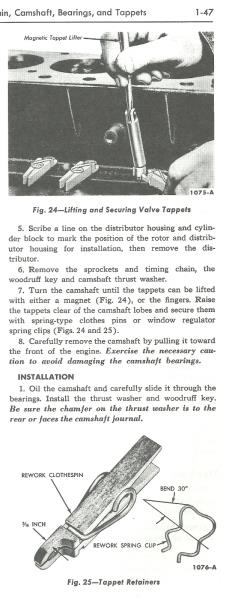
|
|
By Ted - 12 Years Ago
|
|
And here’s the link to the thread showing a picture of the lifter tool used to install the tappets by way of the cam tunnel. Clothes pins still have to be used as the lifters are placed in their respective holes.
http://forums.y-blocksforever.com/FindPost29355.aspx
|
|
By bird55 - 12 Years Ago
|
wooden clothes pins aren't exactly that common anymore either!
Wait! I can see it now-
RARE, early wooden yblock lifter retention tools (Full set) on EBAY buy it now! only $75.
|
|
By Hoosier Hurricane - 12 Years Ago
|
Alan:
You're right. My wife still uses the solar clothes dryer in the summer and has a lot of wooden spring loaded clothes pins. She also has a few made of plastic. We may be sitting on a gold mine!
|
|
By lyonroad - 12 Years Ago
|
|
John, my wife could supply the Canadian market if your wife wants to go International. On this subject, not that I plan to remove a cam this way, I have wondered if you couldn't fabricate a tool with rare earth magnets to hold the lifter up during the cam change. I can visualize the cloths pins slipping off at the worst possible time. However, the problem with magnets, although I see that Ford advocates the use of magnets in the shop manual, is that they attract metal debris. Since the magnet will induce some magnetism into the lifter any metal debris will be difficult to extract and will undoubtedly find its way into the lifter bore. I suppose one could lay a sheet of saran wrap over the lifters before getting the magnet anywhere near them.
|
|
By aussiebill - 12 Years Ago
|
|
CK and his 55Tbird (3/4/2014)
Having a larger base circle and higher rocker ratio creates a stronger structured lobe, being the lobe effectively becomes a smaller raise with increased material. Yet the larger ratio rocker actuates the lift even at the base circle which requires greater precision of manufacture. probably why they started with 1.43:1? So gaining strength at the lobe increases weight at the rocker???
Yet rolling is by far better than rubbing!
And fitting rockers is a darn sit easier than cam shafts in Y blocks!
On that has any of you guys made a clamp/s for lifters on these Y blocks. Like you may have seen brake line clamps, yet more defined and shaped ( peg )to the round lifter which protrudes from the block at lift. I think it would be nice to clamp them raised, once push rods are removed and then the cam could be removed in Car and not having to remove and turn upside down. Alternatively if the tip which protrudes had a hole drilled before fitment they could be used to retain a raised lifter by applying a pin etc.
??????
NO sense reinventing the wheel again ! Wooden clothes pegs WORK! even without being highly modified! i,ve proven this eover 45 yrs.
|
|
By CK and his 55Tbird - 12 Years Ago
|
But that's what Hot Rodding is all about. Finding something close to what you want and tinkering with it until its right.
I guess wooden pegs were great for making peg guns. we used to pinch them from the clothes line
pull one apart for the spring and attach it to an elastic band, and another one was attached to a piece of wood or stick etc.
the spiral of the spring would then be placed in the peg attached to stick and then the elastic would be stretched to the end of the stick. when you pushed on the peg it would release the spiral of spring and the band would send the two flying. It was alway a joy to find the big thick bands as they went further.
Mum used to alway wonder were her rubber gloves went too, though thats another story.
|