|
By Ted - 12 Years Ago
|
Rob sent me a private email asking about the distribution of the fuel from the two sides of the intake manifold. No return email address so I'll just answer the question here.
The left side of the manifold (looking from the drivers seat) feeds cylinders 1, 4, 6, & 7.
The right side of the manifold feeds cylinders 2, 3, 5, & 8.
|
|
By skygazer - 12 Years Ago
|
|
Allowing for firing order, isn't that the same for any dual-plane manifold? The idea is to have even intake pulses on each side of the carb.
|
|
By GREENBIRD56 - 12 Years Ago
|
Yes sir - it is the classic "Cross H" dual plane v8 manifold design- and its a "air-gap" type too.
When I got my T-bird it had plugs showing four had been getting one mixture and the other four another. And they were divided just as the cross H distribution would suggest. I didn't bother fixing the Teapot - I replaced it with the later manifold and a Holley 4160 type carb.
|
|
By Talkwrench - 12 Years Ago
|
Thanks Ted thought you could just reply back on my message..
I asked as I have bought Gunson colortune, I tried it out on my flathead in combination with a vacuum gauge. It works tho' the quality of the unit is questionable 
Would that be the same for a flathead?
|
|
By Ted - 12 Years Ago
|
Talkwrench (6/14/2013)
......I asked as I have bought Gunson colortune, I tried it out on my flathead in combination with a vacuum gauge. It works tho' the quality of the unit is questionable Would that be the same for a flathead? The Flathead fuel distribution layout is the same as the Y in that the left side of the intake feeds cylinders 1,4,6, & 7. The Ford FE (390/428), 385 series engines (429/460), and M-E-L engines (430/462) are reversed though with the right side of the intake manifold feeding cylinders 1,4,6, & 7. In looking at a stock Mopar 273 that's sitting here, that particular manifold is not the typical H pattern in that the left side of the manifold feeds the left cylinders and the right side of the manifold feeds the right cylinders.
|
|
By skygazer - 12 Years Ago
|
|
Ted (6/15/2013)In looking at a stock Mopar 273 that's sitting here, that particular manifold is not the typical H pattern in that the left side of the manifold feeds the left cylinders and the right side of the manifold feeds the right cylinders.
Interesting. A quick look on eBay shows both single plane (Torker/Trantula) and dual plane manifolds available for small block Mopars... and a cross-plane Edelbrock tri-power.
|
|
By John Mummert - 12 Years Ago
|
An interesting thing about the Y-Block intake is that the drivers side runner going forward feeds 1 and 6 so it is 360 degrees as is the runner going to the rear, which feeds 4 and 7. On the Passenger side (LH drive that is) the runner going forward feeds 2 and 5 so it is 180 degrees as is the runner going to the rear, which feeds 3 and 8.So the drivers side is evenly balanced with pulses going front and rear while the passenger side gets 2 pulses going forward then 2 going to the rear.
I wondered about weather this might affect the desired runner size but never came to any real conclusions so I made them the same, or as close as I could get them.
|
|
By Ted - 12 Years Ago
|
skygazer (6/15/2013)
Ted (6/15/2013)In looking at a stock Mopar 273 that's sitting here, that particular manifold is not the typical H pattern in that the left side of the manifold feeds the left cylinders and the right side of the manifold feeds the right cylinders. Interesting. A quick look on eBay shows both single plane (Torker/Trantula) and dual plane manifolds available for small block Mopars... and a cross-plane Edelbrock tri-power.
In looking at another factory Mopar intake sitting here (318 Polysphere), it too has the fuel distribution layout being the same as the previously mentioned Mopar 273 wedge engine. The left side of the carburetor feeds the left cylinders and the right side of the carb feeds the right hand cylinders. Here’s a picture of that particular manifold. 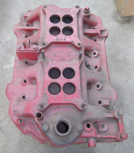
|
|
By pegleg - 12 Years Ago
|
Ted, I think that was pretty much standard for most of the 50's stuff. Especially Mopar. I'm guessin' this intake to be '57-58 Plymouth Fury. I remember a number of dual quad aftermarket intakes with the same layout. Back then I'd imagine any way to get more Carb CFM on an engine had to be a help, Low end power wasn't much of a consideration.
I see that Comp Cams has developed a cam with different duration to accommodate the difference in runner length between the inner four cylinders and the outers. Wonder if that idea would be useful to help the condition John describes. Could be better than a runner volume increase and a corresponding loss in velocity.
|
|
By yalincoln - 12 Years Ago
|
|
yes, the early factory hemi intakes are the same log design. back then they were for all out engines for nascar or drag raceing.
|
|
By Ted - 12 Years Ago
|
|
pegleg (6/22/2013)
...... I see that Comp Cams has developed a cam with different duration to accommodate the difference in runner length between the inner four cylinders and the outers. Wonder if that idea would be useful to help the condition John describes. Could be better than a runner volume increase and a corresponding loss in velocity.
Frank. While those multi-duration cams have been around for awhile in some of the high end racing venues, they are now being offered as a ‘shelf’ item for the masses. The horsepower gains are not much though and a typical gain is about 3HP on your average hopped up street engine. Those magazine guys getting free cams for testing will make a big deal out of the smallest of power gains. Considering how sloppy some of the cam grinders are in matching the lobes from cylinder to cylinder, multi-duration cams are an easy out for explaining away cam grinding variances. . I’m learning that what works for the scrub engines isn’t necessarily what’s best for the Y engines or for that matter, doesn’t work for some of the other main stream engines either. The various engine designs all have their little nuances that makes each one unique. The intake runner lengths on the Y are much more equal in length than a majority of other engine designs which negates the multi-duration camshaft making any difference in this case. Camshaft lobe centerline reduction is also another area that the scrub engines favor while the Y tends to likes a wider lobe centerline angle.
|
|
By Ted - 12 Years Ago
|
|
John Mummert (6/20/2013)
An interesting thing about the Y-Block intake is that the drivers side runner going forward feeds 1 and 6 so it is 360 degrees as is the runner going to the rear, which feeds 4 and 7. On the Passenger side (LH drive that is) the runner going forward feeds 2 and 5 so it is 180 degrees as is the runner going to the rear, which feeds 3 and 8.So the drivers side is evenly balanced with pulses going front and rear while the passenger side gets 2 pulses going forward then 2 going to the rear.
I wondered about whether this might affect the desired runner size but never came to any real conclusions so I made them the same, or as close as I could get them.
John. That sounds like a perfect lead in to making a ‘new design’ dual quad intake. That would help to alleviate some of those nuances you just brought up.
|
|
By GREENBIRD56 - 12 Years Ago
|
And this water flow relocation? Drains from front and rear to maybe equalize chamber temps a bit?
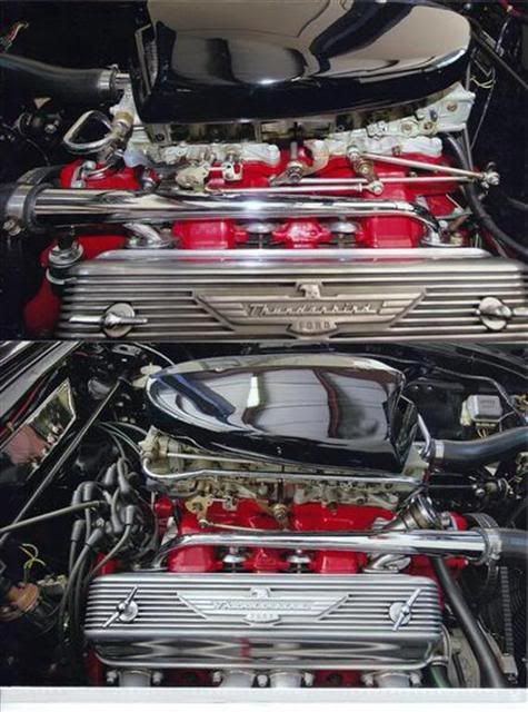
The two 4160 carbs mounted butt to butt are interesting huh?
|
|
By pegleg - 12 Years Ago
|
Frank. While those multi-duration cams have been around for awhile in some of the high end racing venues, they are now being offered as a ‘shelf’ item for the masses. The horsepower gains are not much though and a typical gain is about 3HP on your average hopped up street engine. Those magazine guys getting free cams for testing will make a big deal out of the smallest of power gains. Considering how sloppy some of the cam grinders are in matching the lobes from cylinder to cylinder, multi-duration cams are an easy out for explaining away cam grinding variances. . I’m learning that what works for the scrub engines isn’t necessarily what’s best for the Y engines or for that matter, doesn’t work for some of the other main stream engines either. The various engine designs all have their little nuances that makes each one unique. The intake runner lengths on the Y are much more equal in length than a majority of other engine designs which negates the multi-duration camshaft making any difference in this case. Camshaft lobe centerline reduction is also another area that the scrub engines favor while the Y tends to likes a wider lobe centerline angle.
Ted, Learned the second paragraph long ago with Pontiac Aftermarket Speed Equipment. The stuff was absolute junk on a Pontiac. It was developed For the SBc and just scaled up. Even most Isky stuff didn't work.
I remember you telling me the cam issues before and I'd be hard pressed to Argue. Most of the time when I check one the lift is about right but the timing events are all over the place. I usually attributed that to my methods of checking but the a pattern begins to emerge. Cheap cams are cheap for a reason.
I was thinking about the dual pattern cam to accommodate the difference in cylinder filling (if any) from what John said. The one side being separated by 180 deg's and the other 360. Be a very expensive deal to find out on a dyno.
|
|
By lyonroad - 12 Years Ago
|
Steve posted a picture on this thread of an engine with the water outlets in the front and rear of the heads tied together. Has anyone any thoughts about value of this?
Thanks
|
|
By skygazer - 12 Years Ago
|
Steve's pics are of Doane Spencer's (second) 1955 t-bird... the one that still has a y-block, vs. the original one that now has the 302.
http://www.jalopyjournal.com/forum/attachment.php?attachmentid=390708&d=1198243488
|
|
By gekko13 - 12 Years Ago
|
|
Re. the 273 Mopar intake layout, I recall that back in the day when it was introduced in the Dart body, the objective was to lower the carb mounting pad to clear the hood. I think the subsequent high performance versions got dual plane manifolds. As to the dual pattern camshafts, I believe Clay Smith was one of the first to explore the performance potential in his flathead Ford builds about 60 years ago. He developed specific profiles for specific cylinders.
|
|
By yalincoln - 12 Years Ago
|
|
on Doane's bird he had to mount the carbs back to back because of the metering blocks, they won't fit end to end. he ran water tubes to keep the manifold cooler.
|
|
By Doug T - 12 Years Ago
|
The water manifolds were a modification that go back to the fifties. The rear outlet might be problematic since the head gaskets vastly favor water flow to the rear of the block then up through the big holes at the back of the gasket returning to the front through the heads in the stock setup. The flow could be short circuited though the rear outlet that was added. However one thing for sure is that the front 4 inlet passages to the heads would not be heated by the water passage adjacent to them and they look very cool. Another neat detail was that the heater return to the water pump was adapted to the water bypass on the pump.
Also just noticed that the carb linkage is fully mechanical, with a through link between the carbs.
|
|
By GREENBIRD56 - 12 Years Ago
|
Yes it is the Spencer "clone car" - which I prefer to the newer iteration - they are both pretty neat pieces. I prefer the Y-block version - that outside the frame, side dump exhaust system is a fabulous idea - perfectly executed.
Somewhere I read that the 4 water port set-up was related to NASCAR developments of the era. It would seem possible that "tuning" the four outlets could be used to (somewhat) equalize the four combustion chambers.
The throttle linkage - inverted left to right - is really a sharp bit of work. No vacuum secondary pots either. I finally came to believe the 8 throttle bores all fed a cylinder apiece - and he relied on the two accelerator pump cams to keep everyone happy. Maybe the 50cc pumps with slow continuous discharge rate?
|
|
By yknot - 7 Years Ago
|
Ted, Does the pulse timing apply to fuel injection (throttle body or port)? Is this sketch correct?

|