|
By lameyer - 16 Years Ago
|
|
Does a 292 use the same style of lifters as the 272?
|
|
By Butch Lawson - 16 Years Ago
|
|
239, 256, 272, 292, and 312 all use the same lifters.
|
|
By lameyer - 16 Years Ago
|
|
Thank's
|
|
By PF Arcand - 15 Years Ago
|
|
lamyer: If you are buying new lifters, be careful! There are some off shore lifters out there that are of inferior spec. Might suggest you check with John Mummert in CA or Shumann's Sales in Iowa re reliable spec lifters. Others contributors on the site may have further info...
|
|
By Dennis K. - 15 Years Ago
|
|
There were at least three different types of factory tappets. Two versions of cast iron, the earlier cast iron ones, first used in the 215 6 cyl, had a lower hardness value than the later ones. Then the 5120 steel ones. Certain camshafts, I believe the blower cams and later induction hardened cams, called for the later design cast iron tappets. Regards, Dennis
|
|
By Barry L - 15 Years Ago
|
|
It would be great to get to the bottom of this issue of what lifter really works. Just visited with Jerry C. and saw first hand the carnage of a broken lifter. The lower portion or foot was busted right off and into many pieces. No evidence of valve to head or block interference. The lifter itself had a coarse grain look to it,but I've never seen broken stock one to compare it to ,so I don't know if that was an issue. Any one care to chime in on what they've had luck with??? Re-ground stockers,cast or steel??? Mummert's, shumann's, isky's?? Jerry's set came from Shumann's. Barry
|
|
By Barry L - 15 Years Ago
|
 Here's a pic of the broken lifter from JC 's engine . Barry
|
|
By Dennis K. - 15 Years Ago
|
|
Re the failure, was anyone able to tell if that was the root cause or the effect? I assume that is a cast iron tappet? Do you know who's tappet? OEM Ford, aftermarket, off shore, part number, etc ... . Regards, Dennis
|
|
By marvh - 15 Years Ago
|
Not a pretty sight.
Do you know were the tappet was located in the engine..... by the distributor gear by chance?
Was the foot thickness any different from the rest of the lifters as there were some lifters on the market with a thicker foot than original Ford.
marv
|
|
By Barry L - 15 Years Ago
|
|
I'll have to check with Jerry C. about part numbers. He did say the lifters came from Shumann in a plain white box . Don't know where they were made. The lifter that broke wasn't near the cam gear..it was second cylinder from the rear on the pass. side, can't remember if it was in. or exh. What was left of the lifter foot didn't look too thick, nothing looked obvious as to the cause of breakage. Barry
|
|
By Hoosier Hurricane - 15 Years Ago
|
|
Knowing Jerry and his intended use for this engine, I'm sure it had a very aggressive lobe and plenty of spring pressure. The lifters may have had a lot of edge loading, this may have been the first to fail, the others may have been doomed also. I wonder if he replaced the one lifter and continued his testing. Schumann is proud of the hardness of his lifters, maybe they are hardened all the way through. May be too brittle. Has Jerry had the failed lifter, and possibly an unfailed one, analyzed by a metallurgist?
|
|
By Ted - 15 Years Ago
|
|
I’ll add that pushrod clearance issues at the heads and/or inadequate rocker arm to shaft clearance will destruct a lifter. Although preferences for an undercut at the base of the lifter stem where it connects to the lifter foot seems to be divided, that undercut does allow the lifter to go up fully without jamming in the block at the bottom of the lifter bore. The lifters I use all have this undercut. With all that being said, I’m having no issues with either the Isky or Hylift Johnson tappets for the Y. These lifters were used in the 2009 EMC engine with the over the nose pressures being right at 400 pounds and the camshaft suffered absolutely no wear. Likewise, that same camshaft still looks good after being pulled from the 2010 EMC engine but the valve springs were changed up on the aluminum heads to provide only 330 pounds of over the nose pressure for that particular combination.
|
|
By lameyer - 15 Years Ago
|
|
So what do you guy's think of Elgin valve train part's? I plan on getting a "265 grind" cam from John Mummert, but I already have the other part's. I am putting together a pretty much stock 292 with three "97's" and Sanderson headers, going into a stock 56 F-100. any help from you guys will be appreciated. Thank's
|
|
By Ted - 15 Years Ago
|
|
lameyer (1/2/2011)
So what do you guy's think of Elgin valve train part's? I’ve used Elgin valves without any issues but have no experience with Elgin lifters though. Although hardness testing would be a good indicator of the soundness of the lifter quality, it’s out of the realm of the home mechanic. Visually inspecting each lifter for defects such as voids or porosity and putting a straight edge across each lifter face insuring that each lifter is ground with a ‘crown’ is something that can be done by the home assembler.
|
|
By Dennis K. - 15 Years Ago
|
|
Yes, both hardness and case depth. There are ways of checking with files, but again you need to know what you are doing. The proper way would be to do a metallographic mount and perform a number of meaurements (traverse) for hardness and case depth using a certified hardness tester. What are the concerns with the Ford 5120 Steel tappets? It appears Ford went from cast iron, to steel, then back to cast iron. It appears the later (>1962) Ford induction hardened cams specified cast iron tappets. I would guess that more YB engines were originally equipped with cast iron than steel tappets. Regards, Dennis
|
|
By GREENBIRD56 - 15 Years Ago
|
|
What sort of experimentation has been done with using different materials for the camshaft / lifter interface? All of the materials technology I've seen discussed is traditional for flat tappets - but it might be archaic as well. I've been using this stuff called "ToughMet" for sleeve bearings in unbelievably bad conditions. It commonly comes in a hardness of about 30 Rc - and absolutely resists being "welded to" or scored by iron based materials. Brush Wellman invented it to replace the Berylium Copper used since WWII for aeronautical engineering purposes (ball screws, etc.). This link will show you the engineering properties: http://www.matthey.ch/fileadmin/user_upload/downloads/Fichiers_PDF/Toughmet_Engin_Guide.pdf My contact for using it in the mining machines is Dave Krus - he may be able to tell us if it has been tested or used in a similar service to the cam lifter. Even if the iron or steel lifter body simply was fitted with a shrunk on bronze mushroom "foot" and upper pushrod socket, it might be able to do the job - maybe aluminum bar housing to change the weight?
|
|
By RB - 15 Years Ago
|
|
I was there when Jerry C's lifter failed... His engine was running on a warmup and cam break in cycle with light load at 3000 rpm.. Jerry's cam was not all that aggressive since it was for Engine Masters, 240ish with about .550 lift. Springs 110 and 280 lb. Rocker shafts were rebuilt units from Rocker Arm Specialists and no issues were found there.. It appears to me that the foot of the lifter shattered.. It could be that it was brittle since I do not believe it was loaded excessively.. Certainly not as much as Ted's engine with his higher lift and greater spring pressures. This is the first time I have seen this failure, but it sure was a buzz kill for our EMC hopes.. I would expect that as more folks start pushing valve trains now that the heads can keep up, we may see more of these failures.. I talked to a custom lifter mfg, and someone else had already spoke to them about a tool steel lifter for a Y so we may have something eventually. No doubt it will be pricey. It is my understanding that the hardness between cam and lifter needs to be roughly the same or one will eat the other. Steel rubbing on cast iron is a problem in some other areas (Billet Roller cam on cast iron block face, ....ask me how I know...) , but I think if the hardness is correct, material differences are not a factor Any metalurgists out there?
|
|
By Barry L - 15 Years Ago
|
|
Royce, thanks for the flywheels, I took a pass on the block. As to the lifter, I couldn't see any other cause than just real bad luck. The exposed broken pieces sure looked coarse grained. It would be great to get these issues solved once and for all.I'm slowly assembling my engine and am really hesitant about the lifter compatiblity......too much money in machining and parts to count only on crossed fingers!!! Thanks again, Barry L in Manitoba
|
|
By marvh - 15 Years Ago
|
Barry I sure would not risk it if I was unsure of my lifters origin. So far on the recent engines I have built I have been fortunate enough to find old stock USA mfg lifters.
It appears Ted has had good results with the Isky lifters when using them in the EMC engine. Kind of nice to find there still is an USA manufacturer instead of the off shore stuff. They are more pricey then the ebay stuf out there..... however a blown camshaft is not cheap and you still have to purchase another set of lifters.
John M. wrote awhile back about spring pressures and breaking of lifters. Here is the link.
http://forums.y-blocksforever.com/Topic44380-11-2.aspx#bm44447
marv
|
|
By Oldmics - 15 Years Ago
|
|
Has anybody spoken to Vern about the failure. I gotta admit that I"m a little concerned. Got a fresh engine here waiting for Mummerts heads that have Vern"s "white box" lifters inside. Now I am considering changing those out for some old N.I.B. Wohlert Johnson tappets that I was saving. Wadduya think folks.Safe with Verns products?Or change them out to be safe? Oldmics
|
|
By aussiebill - 15 Years Ago
|
Oldmics (1/4/2011)
Has anybody spoken to Vern about the failure. I gotta admit that I"m a little concerned. Got a fresh engine here waiting for Mummerts heads that have Vern"s "white box" lifters inside. Now I am considering changing those out for some old N.I.B. Wohlert Johnson tappets that I was saving. Wadduya think folks.Safe with Verns products?Or change them out to be safe? Oldmics Mike, saving the good lifters for what? use the good ones while you pursue the others, thats my thoughts. regards bill.
|
|
By speedpro56 - 15 Years Ago
|
|
I always bank on the old original USA stuff .My vote is Wohlert, just good insurence.
|
|
By PF Arcand - 15 Years Ago
|
|
If I read the article correctly in the latest issue, #101 of YBM, J.C.'s engine also suffered a Rocker Arm failure, at about the same time the lifter failed. However, apparently it was not on the same valve! The article doesn't say if the rockers were stock or aftermarket? Seems like there is something strange going on there...
|
|
By PF Arcand - 15 Years Ago
|
|
Ted: A thought based on your observation about the undercut on the lifters you use. If a lifter without sufficient undercut jambed in the block, could that also break a rocker arm? Maybe the lifters Schumann sourced, are oversize under the head?...
|
|
By Ted - 15 Years Ago
|
|
PF Arcand (1/6/2011)
Ted: A thought based on your observation about the undercut on the lifters you use. If a lifter without sufficient undercut jambed in the block, could that also break a rocker arm? Maybe the lifters Schumann sourced, are oversize under the head?...The lifter would have to be jammed extremely hard to create an issue at a rocker arm. Valve spring pressure by itself is expected to be more than adequate to free up a stuck lifter. The lifter foots have an 1/8” or more clearance between the top of the lobes and being in a position to be jammed at the bottom of the block so for a lifter to get jammed on an engine that has already had the valves set, something else is going to be out of kilter. But improperly set valves (way too much clearance) could increase the propensity for jammed lifters. Assuming the radius at the base of the lifter stem is not excessively high, it’s improbable that a jammed lifter is the root of the problem for a broken rocker arm. Having only used the undercut lifters in recent times though, I haven't had an opportunity to examine the radius on the other lifters that are available. On the flip side of all this, I have checked blocks where core shift did have lifters on one side of the block having less clearance in regards to jamming than what the clearance was on the other side of the block. I’ve ended up having to check some of these oddball clearances only because of using camshafts in the Y engines with a 1.150” base circle which has the lifter coming out of the bottom of the bore just enough that if core shift is evident, one lifter bank can be a problem in that the lifters are coming too far out at the bottom of the lifter bore. But back to the undercut. Undercutting is another way to allow for an increase of pressure at a joint before experiencing a failure just as including a generous amount of radius at the same joint does the same. The undercut simply has the advantage of allowing the lifter to go all the way up without allowing the lifter to stick in the lifter bore whereas a radius at the lower end of the lifter stem will allow the lifter to wedge itself at the bottom of the lifter bore if pushed up too high.
|
|
By Hoosier Hurricane - 15 Years Ago
|
|
In reading the YBM article on Jerry's engine, it was stated the broken rocker arm was adjacent to the broken lifter. How about this scenario? The exhaust rocker broke, the valve closed, the cylinder fired, and the exhaust valve could not open again. Cylinder pressure would be quite high, acting against a couple square inches of intake valve head. If cylinder pressure was only 500 psi (and I would expect it to be higher than that) at that point, it would be holding the valve closed with 1000 pounds of force. would this break the lifter as it tried to open the valve?
|
|
By Barry L - 15 Years Ago
|
|
Hi John, The broken rocker was a stock style with bronze bushing and it looked kinda thin after it was bored for the bushing. It broke right on the shaft center-line. This rocker was not next to the faulty lifter, but on the adjacent cylinder. Barry
|
|
By Y block Billy - 15 Years Ago
|
|
Another scenario could be that the broken rocker arm jammed under the adjescent cylinder rocker arm, preventing the valve from opening and forcing too much pressure on the lifter, causing that failure. (a scenario where the weak pushrods would have come in handy if it was the case) Ted, On the undercutting, do you have a picture of how they are undercut? in my world of large machinery, normally when a head shaft failure occurs, its because it was locally made and they did not radius them properly, rather cut square corners on the steps of the shafting. I understand how the radiuses strengthen the joint but not clear how the undercut strengthens them?
|
|
By RB - 15 Years Ago
|
A little bit more about the problems on Jerry's EMC engine...We discovered the broken rocker arm first.. It looks like a failure due to the shaft being bushed with a bronze bushing and the rocker body broke in a thin spot.. The rockers were R&R'd by Rocker Am Specialists. I have a set from them as well but mine are not bushed. I suppose it is possible the the broken rocker somehow jammed into the adjacent cylinder and caused the lifter failure, but I don't think so.. It was later that the lifter failed. . When we discoverd the rocker failure we installed a different rocker shaft and resumed testing.. Our first thought when we dicovered lifter failure was that we had piston to valve interference. We pulled the head expecting to find bent valves and obvious areas of contact. Not so.. the valves were fine... Upon reflection if it had been a contact or interference issue the pushrod should have been bent, it is the weakest link and is normally what fails before any other parts break. Neither was the cam lobe ruined, aside from some scars where the stem of the lifter left scratches as the engine continued to run. . In my mind it was simply a lifter failure.. for what ever reason..The lifter appears to have broke at the stem foot junction. Maybe an internal flaw in the metal. These lifters are undercut at the stem foot intersection.. My understanding is that this is preferable to a sharp corner in this area and is much easier to manufacture than a lifter with a radiused corner.
Given that these failures seem to be rare I would not necessarily point fingers at any one supplier.. Somes stuff just happens.
|
|
By mctim64 - 15 Years Ago
|
I've seen some good bushed rockers in the past but generally I stay away from them. As for lifters I like re-faced old Ford ones. 
|
|
By marvh - 15 Years Ago
|
I have used the bushed rockers and have had no problems either. I like the groove in the bushing for good rocker oiling. I have found the clearances usuallytighter to the shafts than a new no-bushed rocker so less oil pours down the stands.
It is very interesting to see what the professional engine builders on this site who do it for a living, not us occasional weekend engine builders, use for lifters. The common thread I see is that none of them use the "no name" white box lifters when doing an engine build. I am always suspicious whenever a company will not put their name on their product it is almost as if they don't have the confidence in their product or want to be "inrecognito" as they used to say in the kids cartoons.
Here is another link to a list member who had a failed lifter problem awhile back.
http://forums.y-blocksforever.com/Topic31169-3-1.aspx
marv
|
|
By Ted - 15 Years Ago
|
|
Y block Billy (1/8/2011)
Ted, On the undercutting, do you have a picture of how they are undercut? in my world of large machinery, normally when a head shaft failure occurs, its because it was locally made and they did not radius them properly, rather cut square corners on the steps of the shafting. I understand how the radiuses strengthen the joint but not clear how the undercut strengthens them?Bear with me on this as I put some various thoughts together. An undercut removes the potential for a stress riser similarly as does having a generous fillet. You’ll find undercuts used extensively in the gear industry as an undercut will allow more flexibility or ‘bend’ in a given section of material that’s under load than is seen with a radiused fillet. It’s that particular flexibilty that allows a machined part to last longer without a stress related failure.  
Square corners or the lack of any radius or fillet does increase the propensity for stress risers. That’s why when grinding crankshafts it is important the the stone being used is properly dressed so that at least the factory radius is being maintained in the corners or at the fillets. Likewise aftermarket performance crankshafts are supplied with an even larger radius than what the oem’s use. But with those larger radii comes the need for narrower bearings as those radii shorten up the available machined surface that the bearings can ride upon. But the option of restoring usable bearing width to a crankshaft journal comes by using undercuts at the journal edges or fillets. This is not new as many of the older oem Mopar performance crankshafts comes to mind when discussing journals with undercut fillets. These undercuts allow the crankshafts to not have sharp riser points at the journal edges while also eliminating the need for an offset bearing in the connecting rod in which to clear a radiused fillet. Here’s a picture showing undercut fillets on a crankshaft.  But here’s getting back to lifters. When talking about a radius or generous fillet at the junction of where the lifter stem meets the foot, it’s critical that this be as smooth as possible. Any irregularities in this fillet promotes stress risers which in turn just gives the lifter a place to ‘break’. A majority of the Y lifters do have some kind of undercut at the base of the stem as opposed to having a generous fillet or radius. Here’s some pics of various Y lifters.   
 

|
|
By Hoosier Hurricane - 15 Years Ago
|
|
Ted: A late tool shop machinist friend of mine referred to those undercuts as "protected radius". I don't know if this his his term or a commonly used shop term in tool shops. Any toolmakers on thi forum?
|
|
By Dennis K. - 15 Years Ago
|
Hoosier Hurricane (1/10/2011)
Ted: A late tool shop machinist friend of mine referred to those undercuts as "protected radius". I don't know if this his his term or a commonly used shop term in tool shops. Any toolmakers on thi forum? Doesn't appear to be a standard "feature" term. It doesn't appear in the ANSI Standards book on GDT (Geometric Dimensional Tolerancing), ITW Gear books, and others. Perhaps addressed in a Machinery Handbook (I don't have a copy)? "Protected", may have to do with being below the functional diameter and in theory not in contact with anything. The tappet stem has a diameter tolerance of .0006" and a finish of 12 micro. I would expect this would have to be ground and polished to achieve. The radius is .06 and the minor diameter of it is around .013" to .014" below the major (stem) diameter. Probably there for tool clearance when finishing the stem diameter. Before "reinventing the wheel", are there any known concerns with the Ford tappets, early or late cast iron, or 5120 steel? I assume the other tappets on the market were developed by reverse engineering a Ford tappet. Regards, Dennis
|
|
By Y block Billy - 15 Years Ago
|
|
Ted, Dennis, All good points there, I do think some of the undercuts are in things for tool clearance, and yes it may give more flexibility before fatigue occurs, but actually strengthening the joint, I am having a hard time with that one. As Tim does, I have used resurfaced Ford lifters with no problems, I almost don't dare to use anything else with all the horror stories.
|
|
By charliemccraney - 15 Years Ago
|
|
Not strength, flexibility. It essentially makes the part tougher, meaning it can take more before it fails. Tougher is not always stronger.
|
|
By mctim64 - 15 Years Ago
|
|
"Flexibility" is a good term, many things that are made "tougher" break just as easy but as with the radius there is a little give with a smooth transition. I wonder if the term "protected" radius is because it is protected from high production shops that will not radius their stones before grinding a crank. A "rolled" or "relieved" radius/fillet can't be ground out. (most Chrysler products and a lot of the later Ford and GM cranks have this) I'm very leery of Y cranks that have been ground not because undersize cranks are bad but because most of the time the radius has been removed.
|
|
By pegleg - 15 Years Ago
|
|
Bill/ Charlie, In simple terms, so I can understand it. If you flex a 90 degree, sharp inside radius, all of the motion, and therefore stress, is concentrated at the sharp edge. With the undercut it is spread out over the entire radius of the undercut. Metal, especially cast metal, does not flex well. Very low elongation, and the yield strength is very close to the ultimate. It won't bend, it just breaks. clear as mud?
|
|
By charliemccraney - 15 Years Ago
|
I understand. I should rephrase. Flexibility, per Ted's explanation, makes the part tougher but it does not necessarily make it stronger. I would define strength as the amount of force it can withstand and toughness as how long it can withstand a given force before failure.
For instance, we know that a Chevy can be built to meet Y-Block power levels but the Chevy will fail far sooner. In this scenario, the Y Block is tougher. The Chevy has to be built to a lesser power level in order to survive. In this scenario, The Y Block is stronger. 
|
|
By PWH42 - 15 Years Ago
|
|
Great analogy,Charlie!
|
|
By GREENBIRD56 - 15 Years Ago
|
|
There are basically three reasons to provide an undercut radius - the first most obvious being geometrical clearance for a mating part - the previously mentioned illustrations are good. The other (2) are: (1) To avoid a design factor called "Notch Sensitivity" - the harder a part is, the less tolerant it is of grooves, corners and changes of section. A soft mild steel bar is therefore less sensitive to a "notch" than a quenched and tempered chrome/moly bar. 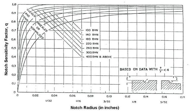
Anyone who has cut glass or seen it cut knows about the effect of the scribed notch on the hard unmarked surface. Or maybe "don't ever leave scratches in a hardened rod or crankshaft journal". (2) To mitigate design factors called " Stress Concentrations" - where the internal stresses of a loaded part are forced to travel around geometric features or be forced into a smaller section. This chart shows the "old school' way of estimating this effect and sizing the parts accordingly. There are times when necking down the intersection - to provide the increased radius of the undercut is just enough to make it work - and last. 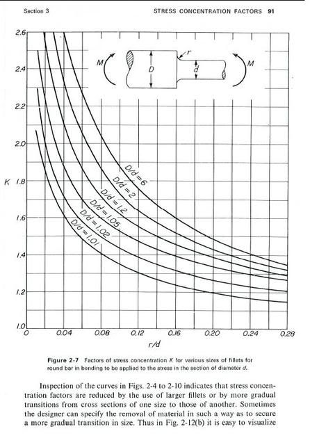
Today - my engineering tech's use a computer design aid called FEA (Finite Element Analysis) to get similar (and more accurate) information when designing parts with very complex geometrical shapes - changes of diameter, corner radii etc. As can be seen in these graphical representations - just about any technique that allows increasing the radius that the internal load or stress must "flow" around - is good.
|
|
By pcmenten - 15 Years Ago
|
As I understand it, it's the lines of strain that get concentrated at a sharp transition that stress the material beyond its strength. When that happens, the metal crystallizes where the strain lines concentrate and a crack starts. The crack causes a further concentration of strain lines at the end of the crack, and the metal cracks more, continuing until the remaining metal is overcome by the strain. I would have expected to see the head of the lifter fall off. That lifter shattered, like it was brittle.
Edit; cryogenic treatments help prevent the fracturing of steel by improving the structure of the grain; the conversion of coarse austenite to Martensite and the improvement of the Martensite to finer grained Martensite. I wonder if giving the lifters a cryo treatment would help prevent the fracturing.
Also, was there enough of the right kind of ZDDP in the oil? ZDDP is a high pressure lubricant.
|
|
By Ted - 15 Years Ago
|
|
Good thread guys! Steve, Thanks for the engineering graphs. Great stuff ! A question for Barry or Royce. Was the lifter badly worn on its face before it shattered? Any wear factor simply makes the lifter face thinner and brings a breakage issue to the forefront.
|
|
By pegleg - 15 Years Ago
|
Also, was there enough of the right kind of ZDDP in the oil? ZDDP is a high pressure lubricant. This doesn't sound like a wear problem, but I wasn't there. Like to see photos of the cam and lifter to see the truama.
|
|
By mctim64 - 15 Years Ago
|
|
pegleg (1/12/2011)
. Like to see photos of the cam and lifter to see the truama.You and me both. Steve, although it hurts my little brain I love the stuff you share with us. 
|
|
By Y block Billy - 15 Years Ago
|
|
Very good stuff Guy's. I thought Royce mentioned there were no evident marks on the cam other than scratches from after the lifter failed. They are not amature builders and I am sure they used the proper assembly and break in lubes. It just looks like the lifter shattered. Royce, Since Jerry doesn't visit here, ask him to look for marks on the bottom of the rocker where that particular lifter failed to see if there is any evidence that the rocker that broke didn't get jammed under there.
|
|
By RB - 15 Years Ago
|
There was no wear pattern of any kind on either the lifter or the cam lobe other than where the lifter stem scored the cam after it broke..Plenty of ZDDP. Jerry used Valvoline racing oil plus a can of Comp Cams break in oil supplement.
I am theorizing that the lifter broke where the stem meets the foot. The foot was then shattered when it hit the spinning crank and ricocheted around the inside of the motor
|
|
By Ted - 15 Years Ago
|
|
Thanks Royce. I think must of us are just grasping for something other than a faulty lifter but from the description, that’s the best scenario for what happened without any more information. Unfortunately in the case of the lifters, you do end up putting them in an engine on blind faith and hope for the best.
|
|
By John Mummert - 15 Years Ago
|
|
I had a long talk we Vern Schumann today and the subject of Jerry's lifter failure came up. It is his opinion and I agree that the likely cause is tight valve guides. This happens far more often then you would think. In a stock Y-Block you would just fold-up the pushrod but in a race engine with high quality pushrods something else will give up. The broken rocker is also an indication the something was seriously wrong. A lot depends on the type of guide used in the head as to the required stem clearance. I never use stainless valves in iron guides so no need to talk about correct clearance there. Iron guides can destroy stainless valves even with chrome plated stems. If using a thin wall bronze guideliner we shoot for .002" clearance on the intake valves and .0022" on exhaust. Some people will tell you that is too loose but experience has shown that guides with .0015" clearance will likely cause trouble in iron heads. If you are using .502" OD bronze guides I would recommend even more clearance. .0022-.0025". The bronze is not dimensionally stable until many heat cycles. When it comes to sizing valve guides my motto is: If the guide has a couple 10,000ths more clearance than might be required the customer will never know it. If it has a couple 10,000ths too little he will hate you. I think that Jerry should disassemble his heads and have someone carefully check the valve guide clearance!!!! BTW, he was not using the aluminum heads I sent him. It is too easy to blame the broken part for a failure. How often is a broken connecting rod really an oiling problem? A broken ring or pounded out rod bearing a detonation problem? In other words, a rod bearing failure could be caused by an ignition or A/F problem. If Jerry had only broken a lifter it would be tempting to blame the lifter but with a broken rocker arm also, something in the valve train was binding up. I have sold 1000s of the Schumann lifters and lifters from the same manufacturer (Vern does QC for the other vendor) with an extremely low failure rate. I did replace 2 for a shop that broke during engine assembly! I suspect the "mechanics" broke them by beating a tight cam gear on and using a lobe/lifter for a back stop. Also, if you are rotating the crank without the full cam assembly bolted on allowing the cam to slip back while rotating, 2 lobes can be forced between lifter heads. I would guess that some lifters have been broken this way. Now you have my 2 cents worth.
|
|
By Ted - 15 Years Ago
|
|
John. Thanks for the input. I have never seen a flat tappet lifter failure here in the shop on any engine that was a result of cam/lifter metalurgy or the oil. When there have been failures, it’s always been another factor such as lifter bore clearance, valve spring pressure, coil bind, retainer to seal clearance, rocker arm geometry, inadequate pushrod clearance, valve stem clearance, camshaft end play, rocker arm to shaft clearance, inadequate prelube, connecting rod to cam lobe clearance, and the list goes on. Because I do get to run in engines built by other shops or individuals on the dyno, I remain cognizant on how easy it is for the simple failures to take place. It typically takes overlooking a single detail among a myriad of items that must be thoroughly checked to propogate a failure. As far as bushed rocker arms, I’ve had repeated breakage problems with those on the FE engines. The bushing reduces the wall thickness of the aluminum around the shaft and just makes the rocker more prone to breaking. Because of this, it’s difficult to just assume that the rocker and the lifter are automatically related. Age of the rockers is also a player and any aluminum rockers that are eight years or older automatically become suspect also. Bronze wall guide clearance has been a topic in the past and it will be interesting to see what Jerry’s and Royce’s final assesment is of the heads once they are pulled apart and examined if not already done so. I still see bronze wall guide clearance problems cropping up in the circle track engines and this is normally traced back to an inexperienced shop or new personnel doing the head work. Learning curves can be expensive to say the least.
|
|
By DANIEL TINDER - 15 Years Ago
|
|
John Mummert (1/14/2011)
If you are using .502" OD bronze guides I would recommend even more clearance. .0022-.0025". The bronze is not dimensionally stable until many heat cycles.
When it comes to sizing valve guides my motto is: If the guide has a couple 10,000ths more clearance than might be required the customer will never know it. If it has a couple 10,000ths too little he will hate you.
John/Ted,
Since determining accurate clearance specs. (within a few 10,000ths) seems to depend on the quality of the measuring tool & experience of the mechanic, can you suggest any specific/extra break-in/run precautions that might possibly help to counteract stainless/bronze guide clearance that COULD be just a bit under the safe margin?
|
|
By Y block Billy - 15 Years Ago
|
|
Thanks for the clarity John, Now I am wondering if it wouldn't be wise to break in an engine with the weaker push rods, just in case there is binding this weakest link would be an easy change, rather than broken lifters, rockers etc.
|
|
By DANIEL TINDER - 15 Years Ago
|
|
Y block Billy (1/16/2011)
Thanks for the clarity John,
Now I am wondering if it wouldn't be wise to break in an engine with the weaker push rods, just in case there is binding this weakest link would be an easy change, rather than broken lifters, rockers etc.
If guides that bind initially would eventually loosen up during break-in, and the more flexible worn pushrods do not create a mismatch/wear problem for certain with rocker/lifter mating surfaces, and the changed geometry resulting from likely head/deck milling would allow enough adjustment without a damaging type of rocker interference, and the the old pushrods don't create another kind of problem during run-in (if they bend or jump out), then sounds like a GREAT idea!
|
|
By Ted - 15 Years Ago
|
|
DANIEL TINDER (1/15/2011)
John/Ted,
Since determining accurate clearance specs. (within a few 10,000ths) seems to depend on the quality of the measuring tool & experience of the mechanic, can you suggest any specific/extra break-in/run precautions that might possibly help to counteract stainless/bronze guide clearance that COULD be just a bit under the safe margin?Tight is tight. Running the engine on the cool side with tight guides might delay a problem but once the valves get hot enough and especially once any throttled load is put on them, the possibility of an exhaust valve sticking in a guide that has minimal clearance is still going to be quite high. Use of the early skinny pushrods might save a lifter at the expense of a doubled up pushrod though but if there’s that much doubt about the guide clearance, it really should be addressed before the engine is fired up. There’s very few places where being on the tight side clearance wise anywhere in an engine is not the potential for a problem versus being on the loose side.
|
|
By DANIEL TINDER - 15 Years Ago
|
|
And babying the motor until some guide wear is realized likely not feasible I assume, since hard acceleration is needed to break in the rings properly?
|
|
By RB - 15 Years Ago
|
Jerry C took the heads to R&R Performance in Spring Lake Park MN.
This is a very reputable race shop that builds a lot of Fords
He had the heads disassembled and the guides checked for clearance.. Brian, the machinist, determined that the clearance was at the minimum he would recommend, however there was no galling or scuffing that would indicate the valve got tight in the guide during testing. Jerry is having additional clearance added per John's recommendation. The guides have thin wall bronze liners. I think Jerry has finally completed the grieving process and is ready to pull the motor apart, replace the injured parts and try again.. He wanted to make sure nobody thought he was pointing fingers at any supplier.. Stuff happens, parts break, sometimes without obvious explanation. The vendor should not be responsible for random failures
Hopefully in the next few months we will have repairs made and be able to resume testing..
|
|
By Ted - 15 Years Ago
|
|
Royce. Was it an intake or exhaust lifter that broke? Just curious but if it was an exhaust lifter, it just adds fire to a tight exhaust guide being the root of the problem. Same question goes for the broken rocker arm but it being bushed makes the cause of breakage in that case questionable even if it was an exhaust rocker. I recognize that the rocker assemblies had been recently R&R’ed by Rocker Specialists but do you know the age of the rocker arm that gave up?
|
|
By RB - 15 Years Ago
|
|
Ted, I checked with Jerry and it was an intake valve that had the lifter failure and the rocker arm failure
|
|
By EBird1 - 15 Years Ago
|
|
Just pulled our 312 down today and surprisingly half the lifter fell our the wrong directions. A definate fatigue break with the FOMCO stamped on the reverse side. 
|
|
By 46yblock - 15 Years Ago
|
That is a  picture. Doubt if it is possible but sure hope worse damage didnt result. Quite the first post! Welcome! picture. Doubt if it is possible but sure hope worse damage didnt result. Quite the first post! Welcome!
|
|
By Ted - 15 Years Ago
|
EBird1 (3/7/2011)
Just pulled our 312 down today and surprisingly half the lifter fell our the wrong directions. A definate fatigue break with the FOMCO stamped on the reverse side. That break looks like it might have occurred during the teardown as there’s very little evidence of wear at the break itself. Not saying this is what happened, but a break like this can take place in pulling out the camshaft aggressively with the lifter not pushed up (or down depending upon your perspective) all the way into its hole. A moderate hit from the side at the lifter foot will snap the lifter shank.
|
|
By EBird1 - 15 Years Ago
|
|
Hate to say it but I think your right. That break does look too clean. No one to blame except me. Hopefully my last mistake. Thanks Dale
|
|
By Y block Billy - 15 Years Ago
|
|
Agree that it is a fresh break, also a break as such would not have time to show wear, I think the head would have just dropped off into the pan. On another note, I don't know if the cast lifters are anything like railroad rail material but I have had an instance where assembling machinery a piece of rail was dropped 6-8' and it broke in half. I have also heard in the old days they could scribe rail where they needed and break the rail there, I have not seen it done personally but beleive it since seing that rail break. Trains ride on that rail and it flexes seriously and takes all kinds of abuse but if scoured shatters like glass. Could Jerrys lifter, or many lifter failures for that matter be caused by a scratch on the surface?
|
|
By John Mummert - 15 Years Ago
|
|
Royce, I would be curious to know what the actual guide clearance on Jerry's heads was. I have seen valves stick at .0016" on a 455 Olds jet boat. Hopefully everythings works out better when its put back together.
|
|
By RB - 15 Years Ago
|
|
John, the clearance on the guides varied from .001 to .0013. Jerry had them all redone to .0013.. The machinist was emphatic that none of the guides had stuck a valve.. The engine only made one short pull so it was never under a sustained load.
|
|
By Ted - 15 Years Ago
|
|
Royce. Pass on to Jerry that I worked on an early model Austin Healy 4 cylinder early last week that had stuck the two center exhaust valves due to being too tight on valve stem clearance. Here’s the full story. I’m involved in this as I had originally recommended and milled the heads 0.055”. This was just prior to the heads going to another shop for new valves, bronze guides, and a valve job. Once that freshly machined head was reinstalled on the engine, the center exhaust valves banged the pistons after 25 minutes of running. This engine was never under a load and simply started missing prior to it being shut off. Not only did the valves whack the heads hard enough to bend, the pushrods also wadded up. The customer then took the removed head back to the shop that did the guide installation and the valve job. That shop said the problem was in the valve to piston clearance which they pointed the problem back to the head milling. When the customer called me on this, I simply told him to bring the engine to me and I would go to the trouble of checking those clearances. Upon doing the checks, I found that the valve to piston clearance was 0.155” on the intakes and over 0.200” on the exhausts; this was more than adequate. Because I now had the cylinder head apart, I checked the stem to guide clearance on the valves that banged the pistons and found them on the tight side at 0.0011” and 0.0016”. Although the hole size in the guides were the same, the two valves in question varied 0.0005” on the stem diameters. And to compound the problem, the exhaust valves stem diameters were slightly larger than the intake valve stem diameters. Final analysis is that both of the center exhaust valves share the same exhaust port so these two valves naturally get hotter than the valves on the end cylinders; subsequently they just ‘seized’ in the guides first due to inadequate clearance to compensate for expansion when hot. In looking at the stems and the guides on the two that bent, there is no evidence of any galling.
|
|
By PF Arcand - 15 Years Ago
|
|
Further on lifter failures; the latest issue of YBM, issue #102, contains the Dyno test of the Church Bros Y-Blk racing engine. It too suffered a lifter failure & block damage. However, it was found that a cam timing error resulted in a valve hitting a piston, and the blow breaking a lifter. Could that have happened to the Christenson engine??
|
|
By RB - 15 Years Ago
|
|
No evidence of valve hitting piston when we pulled the head and no damaged push rods.. Ted I'll pass on your experience,, If I recall it was an intake lifter that broke
|
|
By John Mummert - 15 Years Ago
|
|
Royce, ain't no how, ain't no way I would bolt those heads back on with less than .0018" guide clearance. I would prefer to see .0020" on the exhausts. Intake valves grow too! This isn't Daytona and there isn't a million dollar prize for winning. Tight guides are all risk and no reward. I would rather be down 3 horse power due to loose guides than be down 3 cylinders when the guides sieze up.
|