|
By Ted - 17 Years Ago
|
|
charliemccraney (5/28/2009)
Ted, From your article, it sounds like the first thing I need to do is observe how the roller is traveling across the valve tip. That will tell me if I have to shim or trim the pedestals. When you are setting the geometry, how much do you change the height at one time? Charlie. I’m taking this opportunity to start a new post with your question. Although I have a dial indicator setup that tells me exactly how much the geometry is off by measuring the rocker tip location both at zero and full lift, changing the rocker stand height in 0.025-0.030” increments will allow you to sneak up on the ideal position. When doing the initial setup, using washers of equal thicknesses or valve spring shims work well for raising the height. By working with only two of the stands while doing this also simplies the process. If you’re needing to lower the shaft, then having a pair of stands that are cut 0.150” shorter than stock and then raising these in set increments will allow you to determine what the final height of the stands needs to be. charliemccraney (5/28/2009)
Now that I'm focused on the geometry, I took a closer look at the pattern on the stems. It is slightly off center - the pattern is shifted towards the exhaust side of the heads. Does this tell me anything regarding the geometry?
Due to manufacturing variances and/or any guide work that’s been performed since the heads were new, the rocker tip can be potentially sitting anywhere on top of the valve stem. But if the rocker tip is sitting outboard of the valve stem center at zero lift, then initial indications would be that the shaft is sitting too high. In an ideal world, the rocker tip should be sitting slightly inboard of the valve stem center (towards the intake) when the rocker is at zero lift and where ideal valve train geometry is present. In a less than perfect world, aim for the smallest contact patch on the valve tip between zero and full lift regardless of where the valve tip resides (within reason of course).Another tip is to run a straight edge across the valve stem tips with the rocker assembly removed to insure that all the valve stem tips are indeed at the same height. If you find that these are at varying heights, then it’s going to be difficult to accurately set up the valve train geometry.
|
|
By charliemccraney - 17 Years Ago
|
I finally got to checking the stand height this weekend. It looks like I need to shim them .125" The pattern was about .039" wide at that height. I had a caliper and my eye ball to use for measuring the pattern. Any point above or below that height and the pattern widened. With no shims, the pattern was about .078" wide.
Do these numbers seem to be in any ballpark, Ted?
|
|
By Ted - 17 Years Ago
|
|
Charlie. Sounds like you’ve found the ideal rocker stand height at this point as you’ve found the narrowest sweep pattern on the valve stem tip. While ideal rocker arm geometry will be with the least travel occuring on the valve stem tip, the maximum lift that's possible at the valve will also be achieved. Any rocker stand height adjustments above or below that ideal point will make net lift at the valve also less and this is assuming the pushrod length is being readjusted to correspond with the change in rocker stand heights. The rocker arm sweep mesurement itself will vary depending upon the lobe lift of the camshaft as well as the rocker arm ratio being used so I don’t have a specific travel or sweep value that I’m looking for. Just go for the narrowest sweep and if you have to err to one direction or the other, always err to the rocker shaft sitting at a taller height than on the shorter side (speed secret #1448). Be sure to readjust the pushrod length to keep the rocker arm ratio the same or you’ll lose some of the valve lift gain you get in raising the rocker stand heights in that the rocker ratio will reduce as the adjuster is lowered to reach the same or original length pushrods. While you have your aluminum rocker arms off the vehicle, be sure to check the rocker arm to shaft clearance and make sure you have at least 0.004”. Have seen some recent issues with the aluminum rockers where the clearance has been on the tight side. Be sure to especially check the rockers with the 'centered' adjusters as those are the ones I've had particular issues with.
|
|
By charliemccraney - 17 Years Ago
|
Thanks, Ted.
I was just thinking, I was running out of rocker adjustment at .150" of shim. I probably could not have gone much higher without changing to a longer pushrod. Will the change in the rocker ratio affect my findings significanty? Should I check it again using my adjustable pushrod so that I can maintain the same ratio?
|
|
By Ted - 17 Years Ago
|
|
Charlie. The pushrod being too short will affect the rocker arm geometry to some degree. You’ll likely find that once you increase the pushrod length so that the adjuster is at the original location before raising the shaft assy that the rocker shaft is now sitting slightly on the high side. This is due to an increase in rocker ratio that occurs when raising the rocker adjuster nut to back where it was. In this instance and by increasing the pushrod length, you are restoring the rocker ratio back to where it was before you started relocating the shaft assy for a narrower sweep across the tip of the valve. But if the rocker shaft is no more than ~0.020-0.030” higher than that perfect spot where the sweep is at a minimum value, then I’d suggest leaving it alone as low lift flow at the valve is actually improved by the rocker shaft being biased to the high side. I hope that's not as confusing as it sounds.
|
|
By charliemccraney - 17 Years Ago
|
|
One more thing came to mind. When shimming or trimming the stands, does pushrod clearance usually become a concern?
|
|
By Ted - 17 Years Ago
|
|
Pushrod clearance at the rocker typically isn’t a problem but especially check it when moving the adjuster up as that’s where any clearance issues will come to the forefront.
|
|
By charliemccraney - 17 Years Ago
|
|
Oh, sorry, I meant pushrod to head clearance.
|
|
By charliemccraney - 17 Years Ago
|
|
I checked again with the adjustable pushrod and it seemed to like .150" while maintaining the ratio. That seems like a lot of shim.
|
|
By Ted - 17 Years Ago
|
|
charliemccraney (6/22/2009)
I checked again with the adjustable pushrod and it seemed to like .150" while maintaining the ratio. That seems like a lot of shim.Charlie. Non-stock valves? Anytime longer than stock valves are substituted for the originals, the rocker shafts do need to be adjusted so that they are appropriately higher. The stands on my roadster engine place the shafts ~¼” higher than stock simply due to longer valves which in turn were required by the valve springs which in turn were required by the 0.600” lift at the valve. The dominoe effect was is in full force here in that one thing led to another and another and…… The point being that each change required another and ended up being a cascading effect. As far as pushrod clearance issues in the heads go, they actually diminish as the rocker shafts are raised. Not raising the shafts while going with longer than stock valves will tend to aggravate any existing pushrod clearance problems but by the same token, lengthening the pushrod will also tend to improve the situation by lieu of moving the adjuster more outboard or closer to the intake manifold. I’ve found that these clearance issues when present are typically at the inside bottom of the pushrod hole at the deck surface of the head so I just try to remember to simply grind in these areas while the heads are disassembled and being worked on.
|
|
By charliemccraney - 17 Years Ago
|
|
Ted (6/23/2009)
Charlie, Non-stock valves?
That's probably it. Mummert did the heads. I left it to his discretion.
|
|
By pegleg - 17 Years Ago
|
|
All this talk about raising rocker shafts makes me wonder, is there a market for taller than stock rocker stands? Iron or aluminum? Ted, how come so much lift? thought the ports stopped gaining flow at least .100" before that?
|
|
By Hoosier Hurricane - 17 Years Ago
|
|
Frank: John already has taller stands available. One side is stock height, turn them over and raise the shafts .050. He sent me a set to try on Gordon's engine, but it didn't require taller stands because the valves were stock length.
|
|
By Ted - 17 Years Ago
|
pegleg (6/23/2009)
Ted, how come so much lift? thought the ports stopped gaining flow at least .100" before that? Frank. I’ve heard the same thing about Y heads over the years but I don’t put a lot of credence in flow numbers by themselves. With the Isky 505-T camshaft, I was running 0.537” lift and ran a best of 9.76. Upped the lift with another cam to 0.595” and have run a best of a 9.60 quarter mile et at one track and 9.61 at three other tracks. These are all at leaving the line at 4500 rpms. But it wasn’t as simple as just increasing the lobe lift at the camshaft. The duration was increased from 254° at 0.050” to 263° at 0.050” but this was so I could get a cam profile that was happy with the more aggressive lift. Both cams were ground on the same 108° lobe centers and both installed at 2° advance as measured with no load on the valve train. The valves and springs were also changed to accommodate the higher lift and the rocker arm geometry readjusted to get it back where it belonged. Using the rocker stands from the 302/332 LYB engines simplifies geometry adjustments as they are considerably taller to begin with and give ample room to make geometry adjustments without the use of shims. As an FYI, the LYB rocker stands if turned upside down puts the rocker shafts at the stock Y height. To compensate for the loss of lowend with the increased duration, the heads were milled an additional 0.015” each which increased the static compression ratio from 12½:1 to 13.0:1. This kept cranking compression at the same 210 psi with both cams and in turn kept the 60’ and eighth mile times the same instead of losing some et in the early stretch which otherwise would have had the engine only making up part of the et loss on the big end. This essentially made for an even greater reduction in et than would have been observed otherwise. I think that was the short explanation.
|
|
By pegleg - 17 Years Ago
|
|
Another chink in the armor of "Common Knowledge"! John runs a lot of lift in the Hurricane also, although not that much. His top end speeds seem to bear out what you're saying. You both have better heads than my "stockers" also. Some day we'll have to talk you into a blown engine dyno thrash.
|
|
By charliemccraney - 17 Years Ago
|
|
If higher stands were readily available that I could mill to the height needed, I'd buy them. Don't know that it is a big market, though.
|
|
By Don Woodruff - 17 Years Ago
|
|
Ted, your experience confirms what I have been wondering about for years. Excess lift (lift greater than max flow point) should produce greater flow for an intake cycle. Max flow occurs, stays steady for a bit and then declines as the valve closes. More flow under the curve as we are dealing with a truncated wave whose max value is defined by the head, not the valve opening. A valve lift equal th the point of max airflow yeilds a flow pattern where airflow just reaches a peak and then declines with the valve closing. This peak may not even be max flow as shown by the flowbench due to the inertia of the air. Nice job of compensating for the increased duration of the cam, something not often done thus masking any potential benefits. Just as an aside I know truck pullers are running lifts in excess of 1 inch, using roller cams of course. This is an example of trying to maximize air flow by increasing duration at maximum airflow.
|
|
By 63 Red Stake Bed - 17 Years Ago
|
|
Hopefully related, & relevent; does anyone know the thickness of the oil deflectors that were under the rocker stands on early y blocks? 
|
|
By Hoosier Hurricane - 17 Years Ago
|
|
.038"
|
|
By Ted - 17 Years Ago
|
|
And I found some that are as thick as 0.044”. Thickness likely varied simply due to run of the mill manufacturing variances.
|
|
By speedpro56 - 17 Years Ago
|
|
Were not the Lincoln stands a little taller than the Fords of that era and fit? Could be a remedy.
|
|
By DANIEL TINDER - 17 Years Ago
|
|
Interesting. I only measured one drip tray (came up .040"). Never occurred to me to measure all the rest. Still learning something new every day!
|
|
By Hoosier Hurricane - 17 Years Ago
|
|
Probably depended on how "tight" the stamping press was set up. When I worked in a forge plant, if the parts were a little too thick, they put a shim under one die to make it hit the metal blank harder.
|
|
By charliemccraney - 11 Years Ago
|
Since switching to the Harland Sharpe rockers, I have not yet checked geometry with them, so I started doing that this week. Now I have more sophisticated equipment. I devised and adapter that allows me to use the rod of a dial indicator stand on a stud for a rocker stand, in order to use a dial indicator to measure the actual lift. Now I should get a more accurate indication of what is happening.

I haven't finished, but the results aren't what I was expecting, so I just want to find out from the pros if it seems like I'm on the right track. What I was expecting is a gradual increase, until lift peaks and then a similarly gradual drop in lift. What seems to be happening is practically no change at all in lift. The lift is pretty good, .295" lobe x 1.6 rocker ratio -.015" clearance = .457" and that seems to be in the ball park.
Yesterday I learned the importance of ensuring that I actually start on the base circle - those were some really weird results. I've placed tape on my water pump pulley as reference so I always start from the same position, which is tdc of compression for #5. The pushrod is a micrometer style adjustable and I adjust the pushrod, rather than the rocker adjuster screw to get the valve lash right so that the ratio of the rocker does not change. I check the valve lash after I return to the mark on my pulley to ensure it did not change and make sure the indicator has returned to 0. I've also checked my accuracy with the indicator setup and am able to get repeat readings within a few thousandths, which I hope is acceptable.
Here are the results so far.
Shim, Lift
.000", .448"
.025", .445"
.047", .448"
.072", .447"
.093", .447"
.125", .448"
.150", .450"
.150" is where I stopped for tonight and it does look like it could be getting a bit better so I'll try a little more shim tomorrow. Are those normal results or might I be doing something wrong?
|
|
By Ted - 11 Years Ago
|
Charlie. If you are zero lashing the pushrod, then the target lift at the valve is expected to be 0.472”. If using the water pump pulley as a reference, then I’m assuming you’re simply going forward and backwards for all your readings. If the water pump pulley is not the same diameter as the crankshaft pulley, then constantly rotating the engine in a forward direction will have the water pump reference mark you have out of sync with the crankshaft pulley after one full turn of the engine. At this point, your numbers are not showing the amounts of difference I would have expected to see with the increments of shims you are using. Double check that you have sufficient preload on the dial indicator that will record at least 0.500” of valve retainer travel.
|
|
By charliemccraney - 11 Years Ago
|
I'm adjusting the pushrod for the same .015" lash that I run everyday, not 0 lash. The water pump pulley is the same diameter but I am just going forward, to peak, then backwards to fully closed. I set the indicator at .600 with the valve closed, so open indicates low .150s.
Is what I expect to see correct? A gradual increase to peak and then a gradual drop off? Or perhaps if the stock stands are just right or too tall, simply a decline with more shims.
I'm sure I've checked, but is it possible that some sort of mechanical interference is causing these results, guide to retainer or coil bind? I don't feel any resistance while turning the crank but maybe it's not significant enough to feel, yet.
|
|
By Ted - 11 Years Ago
|
Charlie. Your methodology sounds good. Your 0.457” target for valve lift sounds good with the 0.015” lash value so no problem there. Just double check that the lobe lift is indeed 0.295” so that is not a variable.
|
|
By charliemccraney - 11 Years Ago
|
I checked the lobe lift when I was having the pushrod trouble years ago. That is good. There has been no indication of trouble with lash checks since then.
Assuming that I'm doing things right, how do I interpret the results in terms of the right amount of shim?
|
|
By Ted - 11 Years Ago
|
Charlie. I’ll suggest simply shimming the stands up some more. I would have expected more change in the values than what you are currently seeing though. Increase the stand height to 0.200” and 0.250” heights and see if that makes for a significant change in the valve lift one way or the other.
|
|
By charliemccraney - 11 Years Ago
|
More results, getting better, but still weird, I think.
Shim, lift
.172", .451"
.197", .448"
.222", .452"
.243", .449"
I'm not comfortable using the standard length rocker bolts for any more shim so that's where I stopped tonight.
I took a measurement between the valves to the G head casting. Maybe that can give you a ballpark idea of the length compared to stock? I get 2.004" (2.024" -.020", the ruler). The picture is to show where I made the measurement, not how, I realize it looks like I'm measuring between stems. Mummert might be able to say for sure the length since he did the heads.
Would it be a good idea, after so many checks, to put it back together and run the engine to get oil up to the cam before I continue?

|
|
By charliemccraney - 11 Years Ago
|
I tried again tonight. For some reason, I got results that seem to make sense. I don't know what I did differently. I tackled it two ways, using the dial indicator as before, and looking for a 90 degree relation of the valve stem and roller centerline to shaft centerline at half lift. Does this look more like you would expect, Ted and is my logic about half lift sound?
Tonight's results:
Shim, lift
.197", .453"
.250", .458"
.297", .454
Re the 90 degrees at half lift:
I started by measuring the lift with no shims, and then set it at half lift. I found that a 3/16" allen wrench lined up almost perfectly with the od of the roller axle when set on the spring retainer, so I laid that across the retainer and measured from the od of the rocker shaft to the allen wrench. I measured several times since it's tricky to do while leaning under a hood, to make sure it was accurate. I got about .260". I measured the shaft at about .775" and the roller axle at about .275"
So from center of the roller to the allen wrench is about .138"
That means the rocker shaft centerline needs to be .138" higher than the allen wrench. Center of the shaft is about .388" + .138" = .526" to the od of the shaft at the correct shim height. .526" - .260" = .266" of shim required. I can't do .266" of shim so I started at .250". Since I know it needs to be .526" higher than the allen wrench, I made a gauge out of an index card that I could use to compare against the distance between the wrench and od of the shaft. At .250" it is about perfect. At .197" it is a bit low and at .297" it is a bit high.
To find half lift, using the .250" shims, I start with the valve closed, with the indicator at .600".
Full lift was .142", so lift = .600" - .142" = .458"
.458" / 2 = .229"
So I set the indicator at .229" + .142" = .371" for half lift, to check for the 90 degree relation.
If this is all good, then I will also need taller valve covers in order to use the 1/4" shims
|
|
By Ted - 11 Years Ago
|
|
Charlie. Your second set of dial indicator numbers looks reasonable. Your methodology for the half lift method is a new approach for me but also looks like a good double check to the dial indicator readings. As long as both methods support each other in the results, then all should be good. The quick fix for your valve covers being too shallow for the raised rocker arms would be use double valve cover gaskets. I did that for the 2009 EMC engine which used the stamped steel marine valve covers.
|
|
By charliemccraney - 11 Years Ago
|
I double checked last night before putting the driver side back together and everything looks good at .250". Tonight I'll look at the passenger side just to make sure they're both about the same..
Of course, now I can't find where I read about the mid-lift method for rocker geometry. It is a way to ensure that you have the minimum travel across the valve stem. If an imaginary line between the shaft centerline and roller centerline is perpendicular with the valve stem at half lift, then it should achieve the ideal scenario outlined in your geometry article. The tip will move toward the exhaust side from closed to half lift then back toward the intake side between half lift and full lift and should end up in the same position on the stem closed, and at full lift.
If I find a good article, I'll make a link. It will explain it better than I.
I found this and after reading the first page, it sounds like what I remember, but it doesn't look quite like what I remember.
http://www.sbintl.com/tech_library/articles/rocker_arm_geometry.pdf
|
|
By charliemccraney - 11 Years Ago
|
I checked the passenger's side and am confused again. On the passenger's side I measured more lift with no shims. I only used the .197", .250" and .297" shims and saw the same trend as the driver side, but did not achieve as much as with no shims. I think there must be something I'm doing while getting it set up that is making the measurements unreliable.
Using the other method, with the centerlines perpendicular to the valve stem, I get about the same result as I did on the driver's side. When I do this, I also like the relation of the adjuster screw to the pushrod. At half lift, they're just about in line and at full lift and no lift, the angles are about equal but opposite.
I'm going to go with the second method, 1/4" shims and 8 3/8" effective length pushrods. Hopefully that will be the right choice or at least something that will make it a little better than it is now.
|
|
By Ted - 11 Years Ago
|
|
Charlie. I have to think that your dial indicator setup isn’t consistent when looking for maximum lift. My own method of choice when checking valve train geometry is measuring the sweep across the valve stem tip and targeting for the minimum sweep to obtain perfect optimum geometry. I have found though that by biasing the rockers at a point above where ideal geometry occurs, there is typically a power increase and that comes from the valve lift occurring at a faster movement of the rocker when it’s higher. There are tradeoffs with that though.
|
|
By charliemccraney - 11 Years Ago
|
You said one time, if you're going to err, err on being up to .050" higher than ideal, or something like that.
I got back out there and did it the low tech way, bluing the tip and measuring the scrub pattern and the results indicate that 1/4" should be about right.
Shim, Scrub
0", .110"
.093", .085"
.197", .075"
.250, .065"
.297", .070"
.343", .075"
If the mid-lift method is accurate, and this is not a fluke, that makes for a quick way to get into the ballpark. My previous finding with the Doves support it. I determined that .150" of shim was best for those. The Harland sharp rockers have a larger diameter roller, so everything else being equal, they should need shims which are taller by an amount equal to the difference in the radii of the rollers.
|
|
By charliemccraney - 11 Years Ago
|
I got it done. Since I had the carb loose, I also increased the secondary jets from 65 to 67. I went up quite a lot on the primaries but had not yet touched the secondaries. Rob's experience with his carb give me a great ballpark for where the 570 should be for an engine like mine. I figured it also couldn't hurt since I might have a bit more flow now.
It was about 11:00 pm so I went on a very short drive just to get it warmed up and see if I forgot to tighten any bolts. It pulls freaking hard from about 4000 rpm now. It scared me. I didn't loose traction or anything it was just surprising - not like I'm used to. I looked at my tach and it was at 6 grand in no time. Can't say if it is because of the optimized geometry or jetting change, but something seems to have worked real well. I might start thinking more seriously about a rev limiter. Below 4000 feels about the same as did before.
Tomorrow I go for the official test drive, to a local cruise-in.
|
|
By pintoplumber - 11 Years Ago
|
|
Sounds good Charlie. Is the truck fixed to make the trip to Columbus?
|
|
By pegleg - 11 Years Ago
|
|
Explain how to test the travel across the valve. Blue the rocker?
|
|
By charliemccraney - 11 Years Ago
|
I still have to replace the king pins. Other than that, it's looking good for Columbus. I plan to start on the king pins this week. That should give me some time to put a few miles on everything and make sure it is good to go.
Ted actually has a tool for measuring travel across the tip. Aside from that, blue the tip of the valve, run the valve through a few cycles and I measured the pattern with a caliper. You can see the change if it is really bad but as you get closer to ideal, it becomes more difficult to tell by eye.
|
|
By charliemccraney - 11 Years Ago
|
After driving it a couple days this week, it does seem like it might be a little more zippy at lower revs, but nothing like the improvement at high revs. It sounds different, too. Good different.
For those who are curious, I made the shims out of a strip of 3/4" wide 6061 aluminum. I marked the center of the strip and allowed 1/8" between to cut them apart. A spare rocker stand and transfer punches were used to mark the holes.

I then drilled them.
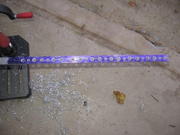
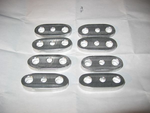
Cut them out and shaped them. Some came out a bit wonky but it's not really a problem - I just make sure a good one is in the oil hole position.
New Smith Brothers pushrods next to an old one for comparison. Because the rocker rotates toward the valve as the stands are raised, pushrods longer than the change in shim height are required. These are 8.362", so a 1/4" change in stand height required about a 3/8" change in pushrod length in this case.

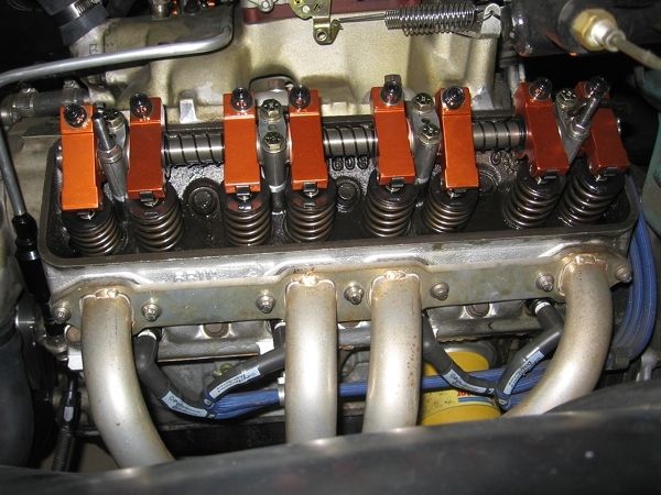
Everything in position.

and installed
I went with valve covers from spotlitekustomaccessories on eBay. The taller covers required that I move the coil which required that I change the fuel line routing - both things that I had been wanting to do but it wasn't really that important. With the old coil position, I could not remove the valve cover with the coil in place. I can remove the valve cover in the new position and a raised base 14" air cleaner should fit, if needed. The fuel lines just look less cluttered and more aesthetically pleasing now, I think.
Before
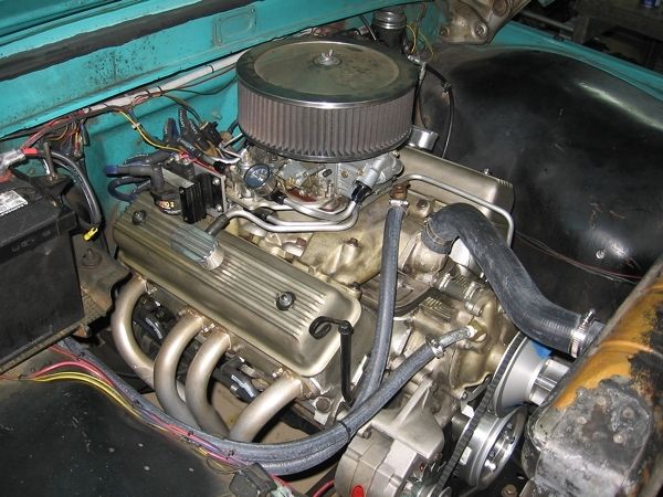
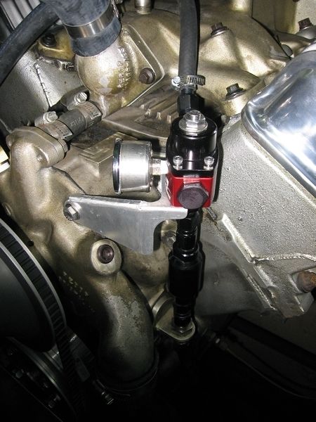
After. Breathers will be used until I've had a chance to do some spacer testing. Once I choose a spacer, PCV will be refitted. The rubber fuel hose will be replaced with a hard line once I choose a spacer.

A bracket to ensure that the regulator stays in place, even though it is mounted right on top of hard fuel fittings. Left plenty of room for a wrench to get at the fittings.
|
|
By miker - 11 Years Ago
|
Charlie,
I really appreciate the detailed info.
Very nice work. Looks really good.
|