|
By charliemccraney - 17 Years Ago
|
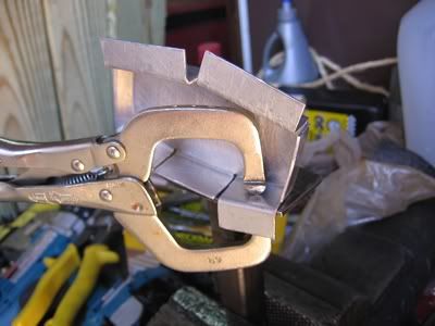
Well, with breathers, there was no need for a baffle. With the pcv valve, the vacuum is enough to draw the oil in to the breather looking housing and drip out onto the valve cover. This is what I've come up with for the baffle.
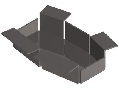
It will be oriented something like this, viewed from the front of the engine:
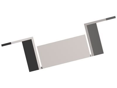
With it in this orientation, the notch at the V on the lower edge (visible in the first image) should allow any oil that manages to get into the baffle to drain.
I'm allowing 5/8" of clearance between the bottom of the PCV housing and the floor of the baffle. The two shorter sides are 1/4" shorter. So I think airflow will be sufficient for that little valve. The overall height is about .800", leaving about .450" clearance for the rocker arms throughout their travel.
I'd like to make sure I get this right the first go round. Is there any baffle science I should be aware of? Anything I should change?
|
|
By simplyconnected - 17 Years Ago
|
|
Yeah Charlie, I might have a dumb idea. After looking at my timing chain cover, it is obvious to me, that nasty, crank-bottom air was flowing up from the front of the oil pan,through those two holes (with the oil dam for the timing chain) and out the down-draft tube. Is there an air path that would circulate the air AROUND the inside of the engine? It looks like with the installation of a new PVC valve, air will come in through the oil breather (if it has one), straight across the valley cover, and out the PVC. What good is that? The idea is to exhaust heavy engine air before it bakes on the sides. We need to suck fresh air down to the bottom of the crank area, and draw nasty air out with the PVC valve. I'm sure a PVC valve will change the air much faster than blow-by is created. Your coalescing pan looks real good. I will think more about this, later. - Dave
|
|
By morgus - 17 Years Ago
|
|
YEAH--NICE DRAWINGS --GOOD THINKING--(YOU DO NEED A BAFFLE WITH PVC OR YOU WILL SUCK IN RAW OIL INTO YOUR ENGINE AND BURN IT (BLUE SMOKE))...BUT MOROSO MAKES ONE FOR SALE AT ANY 'HOT ROD' SHOP---I THINK IT'S $4.OO OR SO....THAT'S WHAT I USED IN MY 55 BIRD (WITH THE ALUM. VALVE COVERS)....I GUESS YOU JUST DID NOT KNOW ABOUT IT--THAT'S WHAT THESE FORUMS ARE FOR- TO SPREAD THE NEWS OF THINGS LIKE THIS,,,,,,, BYE ....ED
|
|
By Duck - 17 Years Ago
|
I was wondering if, with a pcv setup, you could install a filter down on the left-hand side of the block where the road draft set up was, and use a solid (no breather) style fill cap- Seems that would evacuate the crankcase much better, plus the incoming air would be drawn through an actual filter, instead of whatever the fillcap "stuffins' " are. I'm going to try and rig that up if I ever get the motor put together  ... /Duck ... /Duck
|
|
By pcmenten - 17 Years Ago
|
Dave, All the valley covers I've seen have a dam welded underneath them to help redirect the airflow so that it doesn't simply traverse the lifter valley.
Regarding filtered air for circulation through the crankcase, I think someone has already suggested using the type of filler tube that has a sealed cap but has the bung on its side to allow the attachment of an air hose that goes to the carb air filter. This was a common setup on Scrubs in the 60's.
|
|
By simplyconnected - 17 Years Ago
|
Yeah Paul, you're right. Mine has that big diverter, too. I never questioned what it was for.
How do we get fresh air to the bottom of the crankcase? Or, don't you think we need to...?
|
|
By charliemccraney - 17 Years Ago
|
|
morgus (4/21/2009)
YEAH--NICE DRAWINGS --GOOD THINKING--(YOU DO NEED A BAFFLE WITH PVC OR YOU WILL SUCK IN RAW OIL INTO YOUR ENGINE AND BURN IT (BLUE SMOKE))...BUT MOROSO MAKES ONE FOR SALE AT ANY 'HOT ROD' SHOP---I THINK IT'S $4.OO OR SO....THAT'S WHAT I USED IN MY 55 BIRD (WITH THE ALUM. VALVE COVERS)....I GUESS YOU JUST DID NOT KNOW ABOUT IT--THAT'S WHAT THESE FORUMS ARE FOR- TO SPREAD THE NEWS OF THINGS LIKE THIS,,,,,,, BYE ....ED
I'm aware of the moroso baffle. I just like the experience I get by doing it myself.
It seams that the housing for the pcv valve does a good job of separating the oil from the air stream so the oil doesn't make it to the carb - the carb end of the hose is dry. For a system where the hose is connected directly to the valve, it will definitely be a problem.
|
|
By Doug T - 17 Years Ago
|
"Yeah Paul, you're right. Mine has that big diverter, too. I never questioned what it was for.
How do we get fresh air to the bottom of the crankcase? Or, don't you think we need to...? "There was a diagram with some of the Y block introduuction literature that showed the air flow through the engine or at least what FoMoCo thought it was. The air went into the oil filler through the hair filter and down into the valley. The baffle under the valley cover was shown diverting the air flow up into the rocker arm covers through the big holes in the heads. Then back down into the valley through the rest of the holes in the head and then through the holes at the back of the valley around the dist drive and into the crank case. This was all motovated by the road draft tube on the side of the block at least in 54. This design didn't seem to work too well for the rocker arm covers and the valley of the engine as anyone who has disassembled an early gunked up motor can attest. By end of production FoMoCo put the PCV pickup at the rear of the valley cover with at least one or two other variants. The PCV valve was on the front of the 2 bbl manifold. But as far as I know the baffle stayed in the same place as did the big holes around the pushrods.
.
Now two questions:
How do you paste part of a previous post which is highlighted in white, in a reply? What I did in this post was "cut and paste" but it isn't as clear.
Also Charlie what drawing software are you using?
|
|
By charliemccraney - 17 Years Ago
|
|
Doug T (4/22/2009)
Now two questions:
How do you paste part of a previous post which is highlighted in white,in a reply?What I did in this post was "cut and paste" but it isn't as clear.
Also Charlie what drawing software are you using?
See the five buttons in the upper right of each post? Click the one identified as Quote for the post you want to quote.
I'm using Turbocad 9.5 Professional.
|
|
By Doug T - 17 Years Ago
|
See the five buttons in the upper right of each post? Click the one identified as Quote for the post you want to quote.
I'm using Turbocad 9.5 Professional.
OK thanks so much it is great to have the topic that prompted the response to see while you are working on an answer. Oops still doesn't look the same!
|
|
By charliemccraney - 17 Years Ago
|
|
Edit the first [/quote] so that it is [quote] and it should work. Not sure how that happened.
|
|
By charliemccraney - 17 Years Ago
|
I made the baffle tonight!
 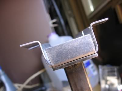
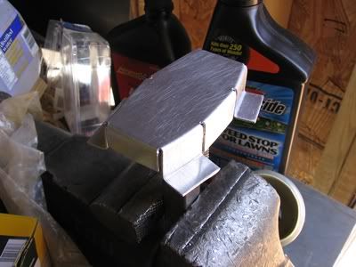
The tricky part was figuring out how to make all of the bends. My solution was to make a steel form around which I can shape the baffle. The form surface is made with 12 gauge mild steel. I made sure to remove an burs and sharp edges to prevent it from cutting the aluminum. I had a piece of scrap 3/4" square tubing which I welded to the bottom in order to clamp the tool into a vise.

The aluminum blank is clamped to the form and the flanges are hammered into shape. I forgot to take picture while making it so these will have to do.
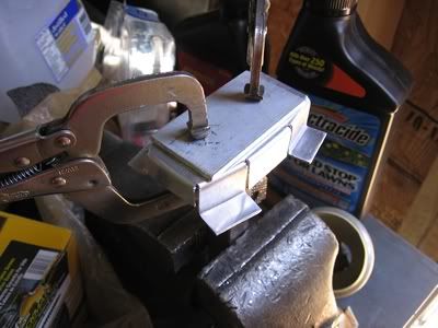 
It worked great for the 18 gauge aluminum!
Tomorrow, I plan to dry fit it. I'll use some duct tape to hold it in place while I turn the engine over by hand to make sure everything clears. Two of the angles were a bit of an educated guess. If it clears, I'll swing by my friend's shop and get it welded in place.
|
|
By charliemccraney - 12 Years Ago
|
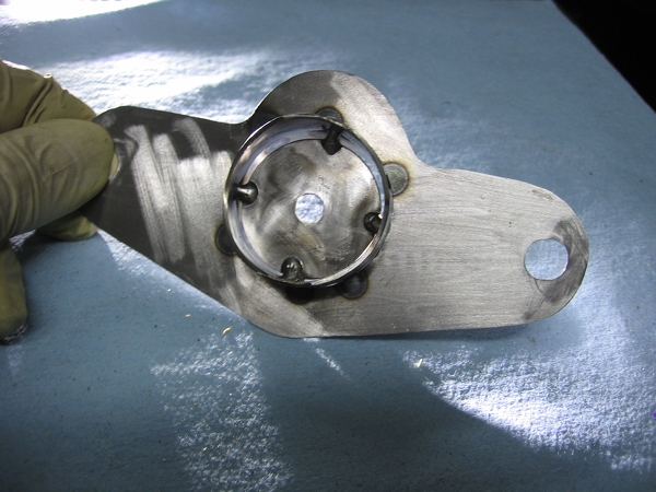
So... I finally got to work on this again. I came up with another method that I think can work out better. It will be removable which will be good for changes or modifications. I simply made some studs for the rocker stands and the baffle mounts to the studs. It is a simple design, 1 1/2" tubing which the grommet fits inside and there is about 1/16" clearance between the top of the tube and the valve cover and clearance where necessary for the rocker arms. I haven't put it to the test yet but I did take it for a spin up the road and nothing blew up, so that's good 

|
|
By Outlaw56 - 12 Years Ago
|
|
You do awesome work Charlie.
|
|
By charliemccraney - 11 Years Ago
|
So, this didn't seem to help at all. I thought maybe it is still able to draw oil in from below the baffle plate so I revised the design by welding the piece I cut out with a hole saw.
That still didn't help, so I figured that it must be flowing across the roof of the valve cover. Since the baffle tube is not a perfect seal against the top of the valve cover, when that oil gets to the grommet, it flows across the grommet and to the pcv valve inlet.
I remembered the baffled grommets I tried a long time ago that seemed to severely restrict the flow of the breathers. I still had them and the plan was to simply trim them so they are no longer baffled, but simply a long tube to extend from the roof of the valve cover, in hopes that the oil flow would be diverted far enough away from the pcv valve inlet that it does not get sucked in. While investigating the grommets, I found the reason for the poor previous performance. A very thin film of rubber is left from the molding process which blocks the flow. I trimmed that with an xacto knife, and tried it. The baffled grommet is too long to use in conjunction with my baffle, so it is only the baffled grommet. Flow through the baffled grommet seems to be good now and it has solved the problem as the top of the valve cover is finally dry.
|