|
By KULTULZ - 5 Years Ago
|
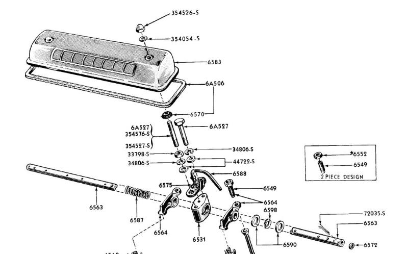
Is the following ENGINEERING/PARTS ILL showing the hold down grommet position correct?
|
|
By BamaBob - 5 Years Ago
|
|
It appears to show the grommet installed from the underside, which would be incorrect. It wouldn't seal in that position.
|
|
By KULTULZ - 5 Years Ago
|
THANX! for that.
Been so long I let FORD fool me.
How can they release an ENGINEERING/PARTS ILL and no one has caught it?
|
|
By MoonShadow - 5 Years Ago
|
|
That explains where that comes from. A lot of people have told me that over the years. When I put on some aluminum covers I tried it. I put a jam nut under the washer set to the height to allow solid contact with the washers. It actually didn't work badly but it took a lot of trial and error to get the valve cover gaskets and hold down at enough pressure to seal. Went back to putting the rubber washers on top.
|
|
By DANIEL TINDER - 5 Years Ago
|
KULTULZ (2/16/2021)
Been so long I let FORD fool me. How can they release an ENGINEERING/PARTS ILL and no one has caught it?
Likely all the drawings were done long before any parts were being produced/assembled (?).
BTW: They also drew the T-Bird’s Rt. ex. manifold heat valve upside down.
|
|
By 57RancheroJim - 5 Years Ago
|
I think because this is a parts illustration rather then a shop manual picture they were trying to show that the valve cover gasket and the two grommets are supplied together. They probably could have done it a little better. The parts person only has to get you the right parts, he doesn't care how you put it together 
|
|
By paul2748 - 5 Years Ago
|
I did the same as Moonshadow when I first put the engine together because I saw the diagram. Ran into the same problems. I got everything so no leaks, but it was a pain to pull and install the covers so I eventually changed them
|
|
By KULTULZ - 5 Years Ago
|
|
Likely all the drawings were done long before any parts were being produced/assembled (?).
If you look at the 6549 ADJ SCREWS, it shows early and late (mid-1956/ ). So the ILL has to be at least mid-1956 production. FORD PARTS DIVISION used modified ENGINEERING DRAWINGS (as well as SERVICE DIVISION for SHOP MANUALS).
How was this released with no one catching it?
|
|
By 57RancheroJim - 5 Years Ago
|
I don't know how it worked in parts departments but the shop manuals have a lot of errors and when caught and other service changes happened they put out REVISIONS to correct it. Unfortunately only dealers got the revisions and a person like myself with no connection to a dealer never get them.
|
|
By KULTULZ - 5 Years Ago
|
Correct. Service Manuals were printed on the quarter year, corrections included. Same with PARTS MANUALS, upgrades every quarter. Corrected service procedures were also released with SERVICE BULLETINS.
But another poster showed a page from his 54 SHOP MANUAL (don't know if FORD or MERC) that showed the correct sequence.
It may be the ILL is first print and the later 56/ rocker arm adjusting screw ILL inserted on that particular ILL.
BASIC PN 6A506 is the BPN for a valve cover set incl grommets. The grommet is also available separately.
Never say never regarding FOMOCO.
|