One of the issues with a true 180° header is getting the various tubes to crossover to opposite banks in a chassis while maintaining equal length tubes. The Ford GT40 cars had the tubes crossing over at the top of the engine and used two collectors. I’ve dealt with some circle track engines using a header design that uses only one collector with all eight tubes going into that single collector. But it’s still a plumbers’ nightmare to get all those tubes snaked where you want them and maintain some semblance of equal lengths on the tubes.
As you mention for the Ford Y, cylinders 2 &3 would need to exhaust out the left side collector while cylinders 6 & 7 would need to exhaust out the right side header to capitalize on a 180° header design. My current race car chassis restricts me from doing the crossover of the tubes so I take a different approach. Because cylinder #6 is restricted by a pressure build up that occurred by cylinder #8 firing immediately before it, I simply shorten the tube for cylinder #8 and lengthen the tube for cylinder #6 to give the exhaust pulse created by cylinder #8 additional time to clear before cylinder #6 catches up to it. Likewise, cylinder #2 has a shorter tube while cylinder #1 is longer for the same reasons. By luck of the draw, the Y firing order allows the appropriate tubes to be shorter and longer which matches to some degree their placements in the engine bay. This makes building the headers somewhat simpler when placing the short/long tubes where they need to be.
To take the header design one step further, the tubes are positioned in the collector so they exhaust in a circular pattern to take advantage of the scavenging pattern set up in the collector by the rotational exhausting from the tubes. While it technically doesn’t make any difference, I have one bank exhausting in a clockwise fashion while the opposite bank exhausts in a counter clockwise fashion. While it seems intuitive that this was done to counteract the torque that’s created by having both sides exhausting the same direction, the direction of rotation really isn’t a player here.
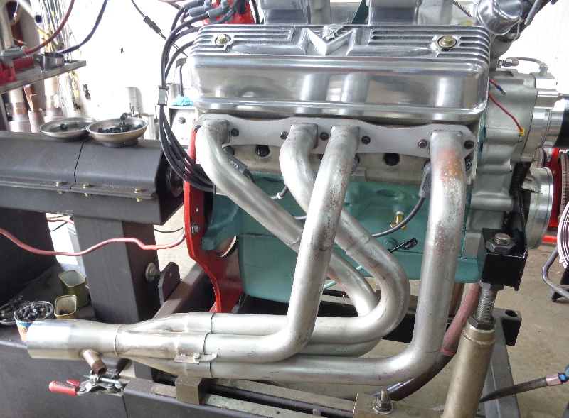
Here’s a picture of the long/short tube design along with the rotational exhausting of the tubes within the collector. This header also utilizes a merge collector.
|